Continue to Site

Welcome to EDAboard.com

Welcome to our site! EDAboard.com is an international Electronics Discussion Forum focused on EDA software, circuits, schematics, books, theory, papers, asic, pld, 8051, DSP, Network, RF, Analog Design, PCB, Service Manuals... and a whole lot more! To participate you need to register. Registration is free. Click here to register now.

[SOLVED] [Moved]: LC tank oscillator. How can I choose the ratio L and C ?

Status
Not open for further replies.

palmeiras

Full Member level 6
Joined
Feb 22, 2010
Messages
375
Helped
61
Reputation
122
Reaction score
50
Trophy points
1,308
Location
South America
Activity points
4,199
Hi guys,

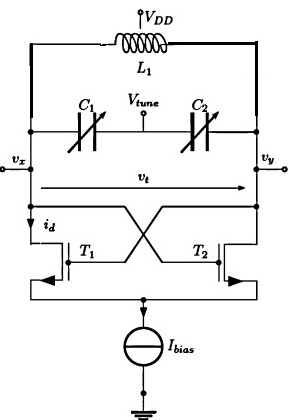
When designing a traditional LC tank oscillator whose oscillation frequency is given by 1/√LC:

How can I chose the ratio L and C? Considering that I have no area restriction and I can design the inductor with any size and shape.

Thanks! best regards.
 

Re: LC tank oscillator. How can I choose the ratio L and C ?

Determine the parallel load R 1st and desired gain up to 100 for practical considerations.

The given Freq. , R, Q, there is only one value of L & C such that ω=1 / √(LC)

But if you have highest R possible, then the leakage Rp of cap is used.

The inductor will have a series resistance Rs which can be neglected if Load R »Q*Rs, otherwise, it will reduce the Q.

If you like online calculators, search for "RLC calc online"
If your prefer quick lookup graphs, search for "RLC nomograph" with lower accuracy but a better understanding of impedance ratios and Q which can be read from the intersections. Of Z at resonance and the higher R load for the Q ratio.
Converse is true for Series resonance.

the factor is choice of L must have a self resonant frequency SRF >> Fosc. (>10x) otherwise self capacitance affects tuning to a lower f.
 
Re: LC tank oscillator. How can I choose the ratio L and C ?

For lower noise select smallest L and gretaer C to reduce the tank circuit's losses.
But there is an optimum point while losses are decreasing and simultaneosly oscillator conditions are met.
 
Re: LC tank oscillator. How can I choose the ratio L and C ?

A lot depends on the purpose of the oscillator.
If its a low power frequency source, such as a local oscillator in a receiver, or for a test signal generator, usually higher Q will give a more stable frequency with less distortion and harmonics.

If it has significant power and needs to drive a load, the Q is generally made lower to reduce losses and increase efficiency.

The LC ratio determines the impedance, as well as the loaded Q.
And that depends on the circuit and the application.
 
Re: LC tank oscillator. How can I choose the ratio L and C ?

Thanks very much, guys!

In this example, I was interested on designing the LC-tank with the lowest possible noise (better phase noise performance) it is the purpose (power is not an issue).

Big Boss,
Please, could you clarify?
why smallest L leads to lowest noise?
(i ) I guess that Increasing L (inductor length or the number of turns) will increase RS (inductor series resistance), but I guess the ratio L/Rs tends to be the same. Is that correct?
(ii) which oscillator conditions are you talking about? And why decreasing L will have impact on it? As soon my negative resistance (RP) compensate the positive (RP) of the tank (equivalent resistance is infinite), the oscillation is guaranteed.

Warpspeed,
(i) please, could you clarify? it is not clear how the LC ratio will defines the loaded Q? Capacitor implemented as MiM cap or Inductor, which of these have the worse Q? I guess is the inductor.
But I do not understand why decreasing L will improve the LC-tank Q.
 

Re: LC tank oscillator. How can I choose the ratio L and C ?

Highest Q is obtained using an ideal current source and high impedance R load.
Q is always this ratio of R/Xc=R/XL at resonance. Usually a transistor collector driver is used with feedback for bias and output for linearity.

But LC temperature drift and self capacitance limits practical Q limits of 100 with P250 caps to match N250 copper chokes. (as I recall , which are rare in large values. beyond hundreds of pF)

A better design for low phase noise is a ceramic resonator with Q of 1k~10k or a crystal with Q of 10k up to 100k for expensive SC cuts with appropriate temperature compensation

Many other choices include dielectric resonators, SAW resonators, then there are heliix resonators , stripline resonators, patch resonators, etc etc.

Costs & performance depends on volume and application specific requirements, which are so far unspecified.
 
Re: LC tank oscillator. How can I choose the ratio L and C ?

Warpspeed,
(i) please, could you clarify? it is not clear how the LC ratio will defines the loaded Q? Capacitor implemented as MiM cap or Inductor, which of these have the worse Q? I guess is the inductor.
But I do not understand why decreasing L will improve the LC-tank Q.
Any tuned circuit is going to have some losses.

Those could be due to series resistance in the components themselves, or shunt resistance of either some load, or whatever drives the tuned circuit.
You need to look at the entire system, the circuitry around the tuned circuit, as well as the components themselves within the tuned circuit, as well as the operating frequency and intended application.

For least phase noise, you definitely need the highest Q circuit with absolutely minimal losses. Without knowing the circuit topology, the impedances or loadings involved, its not possible to suggest an optimum LC ratio.

For instance, inductors may be either the most lossy, or least lossy part of the circuit, it depends on a whole lot of other factors.
Likewise with capacitor types, as well as values.

All you have told us about this is that it is a traditional tuned tank circuit.

The frequency also has a strong bearing on selecting components.
An air cored inductor would very likely give lowest losses at higher frequencies.
But at much lower frequencies some kind of magnetic core will greatly reduce the number of turns and may or may not reduce overall losses, because the core material itself introduces new loss mechanisms.
At 10Hz a huge laminated iron core might be expected to produce the lowest loss inductor.

Another problem quite apart from phase noise is frequency stability.
That may or may not be of even greater importance.
 
Re: LC tank oscillator. How can I choose the ratio L and C ?


- - - Updated - - -

Thanks Tony for your attention. I´m sorry, I did not give details about the topology. The attached figure shows the topology I´m talking about.

Looking this topology, could you say if the it is the inductor or the capacitor the most lossy element? And what it would be a good ratio aiming to achieve the best phase noise performance?

- - - Updated - - -

frequency of operation is 2.5 GHz

- - - Updated - - -

Thanks, SunnySkyguy for your reply. I´m sorry for not giving details. I´m talking about an integrated circuit where I´m going to design the inductor. The inductor Q is less ~ 10 for the cmos process I´m using. So I´m sure how big the inductor must be for a given oscillation frequency.
 

Re: LC tank oscillator. How can I choose the ratio L and C ?

Thanks for the circuit, it helps a great deal.

The difficulty with that chip, as I see it, is that the mosfets alternately go into hard conduction, its basically an astable flip flop.
As each mosfet is turned hard on, it directly shunts half the tuned circuit, loading it down and reducing the loaded Q somewhat.

So I would expect it needs to be a fairly low impedance tuned circuit, high C low L. But at that frequency, the actual physical components tend to merge with stray L and C anyway, so its really probably more about coming up with a practical workable physical layout than anything else.

If you can dig up the application notes on the specific chip, there should be some pretty good guidance as to what is required.

I am an old Ham radio guy, but this type of circuit and its relatively high operating frequency are not something I have had any personal practical experience with.
 
Re: LC tank oscillator. How can I choose the ratio L and C ?

I don't know about the nonlinear current of the waveform, your components and current source, but I would start with 12nH , center-tapped and 0.5pF with Vtune grounded for 2.5GHz
 
Hi SunnySky guy! Why have you suggested these values? could you explain the tradeoff C vs L ?
 

Hi,

oscillation frequency is given by 1/√LC:

it should be: oscillation frequency is given by 1/( 2 x Pi x √LC)

****
you asked about the single values.
For me i found a rule of thumb, but i don´t know if it fits to your problem.
I chosse C (or L) to be the impedance in a practicable value. For very high frequency i choose it to be 100 Ohms for example.
(for oscillators in the MHz range i´d choose 1k..10k, for lower power systems even higher)
It´s just to be sure it is not in the range of mOhms or MOhms...

So for 2.5GHz i´d chose C = 1 / ( 2 * Pi * 2.5G * 100) = 0.64pF. Divide this value by 3 or multiply it by 3 .... it shouldn´t make much difference.

For sure you have to use the chosen value to calculate L.

Hope this helps.

Klaus
 
The choice of L & C is limited by the interwinding capacitance or SRF of printed coil, junction capacitance of active device and filter impedance results will be in the 100 Ohm range. I chose values for higher resonant frequency because designers tend to underestimate effects of stray geometry capacitance.

Since PCB dielectric and conductor width values are wide tolerance, this design would not be vary stable with tolerances unless on ceramic substrate.

Stripline patch resonator antenna methods will be much lower impedance with lower inductance and more capacitance and matched by stripline feed point.

Also consider MEMS dielectric resonator.
 
Thank you very much, Guys!! Great explanations.

KlausST, why have you chose the capacitor impedance to be 100 ohm? What are the trade-off in this choice? Why do we want low impedance? What is the issue with high impedance in this node? At resonance frequency, the impedance will be only given by RP. (we are going to connected -RP implemented by active devices).
 

The resonant impedance is determined by either L or C as both are equal but opposite phase at resonance.

The current source and dynamic switch affects the Q Which is a higher impedance and also affects unwanted load capacitance.... In this case a negative Resistance with gain.
 
Hi,

why have you chose the capacitor impedance to be 100 ohm?

Yes i know this has nothing to do with resonant impedance of combined LC, it is just the single impedance of C and thus the single impedance of L, too.

Call it personal taste.... (maybe i chose this range of value because of antenna impedance or PCB trace impedance. 50 Ohms up to 150 Ohms are very common with HF circuits)

I see values in the milliOhms may be problematic because of high influence of (unwanted) serial impedances...
And i see values in the high megaOhms similar problematic, because it may be easily influenced by noise around...

Klaus
 
You'll have a certain amount of Amperes traveling through the inductors.

The inductors must create sufficient voltage swing, resulting in one transistor shutting off while the other turns on.

A smaller Henry value is associated with greater current.

If you have very small current running through the circuit, then increase L, decrease C.

This circuit has two modes of operation. One is an astable vibrator. The other is as an LCC tank circuit. You may need to take steps to prevent one of the modes.
 
Re: LC tank oscillator. How can I choose the ratio L and C ?

Big Boss,
Please, could you clarify?
why smallest L leads to lowest noise?
(i ) I guess that Increasing L (inductor length or the number of turns) will increase RS (inductor series resistance), but I guess the ratio L/Rs tends to be the same. Is that correct?
(ii) which oscillator conditions are you talking about? And why decreasing L will have impact on it? As soon my negative resistance (RP) compensate the positive (RP) of the tank (equivalent resistance is infinite), the oscillation is guaranteed.

Negative resistance is not a single parameter on the functionality of the oscillator.The oscillator needs to satisfy necessary and sufficient conditions for stable oscillations.The huge negative resistance may not guarantee you that your oscillator will always work stable.
Negative resistance is necessary but not sufficient.In the closed loop, the desired phase shift should be occured and the loop gain must be greater than unity.These are desired conditions, not negative resistance only..
 
Re: LC tank oscillator. How can I choose the ratio L and C ?

Negative resistance is not a single parameter on the functionality of the oscillator.The oscillator needs to satisfy necessary and sufficient conditions for stable oscillations.The huge negative resistance may not guarantee you that your oscillator will always work stable.
Negative resistance is necessary but not sufficient.In the closed loop, the desired phase shift should be occured and the loop gain must be greater than unity.These are desired conditions, not negative resistance only..

I think, this statement needs clarification.

There are two alternative forms to formulate the oscillation criterion (necessary but not sufficient):
1.) Unity Loop gain for one single frequency, or
2.) Negative resistance "meets" positive resistance for one single frequency.

That means: Each oscillator circuit can be seen and described either in form (1) or in form (2).
However, in some cases it seems to be easier and more logical to use form (1) and in other cases form (2).

Example: In most cases. the classical WIEN oscillator is seen as a closed-loop consusting of an RC-bandpass (transfer maximum 1/3) and an amplifier with a gain of three.
However, it is not a problem to use the negative-resistance description to show that the circuit can oscillate at the same frequency.

- - - Updated - - -

Sorry - at point 2.) I forgot to add that both resistances (positive/negative) must have the same value at the desired oscillation frequency.
(In practice, for a safe start of oscillations both criteria must be slightly "overfulfilled")
 
Status
Not open for further replies.

Part and Inventory Search

Welcome to EDABoard.com

Sponsor

Back
Top