Continue to Site

Welcome to EDAboard.com

Welcome to our site! EDAboard.com is an international Electronics Discussion Forum focused on EDA software, circuits, schematics, books, theory, papers, asic, pld, 8051, DSP, Network, RF, Analog Design, PCB, Service Manuals... and a whole lot more! To participate you need to register. Registration is free. Click here to register now.

[Moved] Issues with PIC16f877A on the Breadboard

Status
Not open for further replies.

savannahlexus

Newbie level 4
Joined
Oct 5, 2011
Messages
6
Helped
0
Reputation
0
Reaction score
0
Trophy points
1,281
Activity points
1,379
I'm totally a beginner in electronics and PIC programming. I encountered similar problem when I start to wire my first PIC16F877A circuit on breadboard. I have programmed the microprocessor with a simple LED light on logic and verified the program works on my prototype development board. However I wire the circuit on breadboard, the LED is not turned on. I've verified the power supply voltage, LED, oscillator separately and they all works independently.

Here is my breadboard circuit photo: **broken link removed**


Please advise how I can tackle the problem.
 

Re: how to wire up PIC16f877a on the breadboard ???

@savannahlexus mmmm sadly i dont have my datasheet at hand, but, as far as i remember there are a few thing you must correct on your circuit...

VCC is pin 32 not 33
GND is pin 31 not 32!!!!!!!! (this could have burned your pic... check it out inmediatly!!!!!)

also its recommended to wire the extra VCC/GND pins on 11 / 12
also the crystal and 15 pF caps should be on pins 13 & 14 !!!!!!!!!!!!! not 12 / 13...

also indicate which output does the led works... actually its on RD6, is it correct????????


aaaaaaaaaaaaaand don't forget to set a pull-up on RESET ( pin1) its a 10K resistor form PIn 1 to VCC(5v)

please check all this things... and all the config related (EXT OSC, )
 

Re: Issues with PIC16f877A on the Breadboard

Check the voltage on the chip itself. You may find the +/_ bus needs jumpers.

Hope this helps
 

Re: Issues with PIC16f877A on the Breadboard

There appears to be several issues with the actual wiring of the circuit.

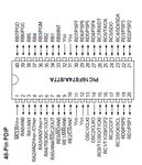
You need to apply 5V and GND to both sets of Vdd and Vss pins. Compare your connections of Vdd, Vss, OSC1 and OSC2 to the pinout provided, they appear to be connected to the wrong pins.

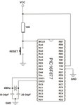
You also need a pullup resister of around 10KΩ between MCLR pin and 5V. I would also recommend a 0.1µF capacitor across the Vdd and Vss pins as close to the device as possible.

Reference the PIC16F87XA Data Sheet when wiring your circuit.

circuit.jpgPIC16F877A.jpgMinimumCircuit.jpg

You also should upload or post your code so that we may take a look at it.

BigDog
 
bigdogguru,
In your last diagram, you have not connected the VDD and VSS pins (pins 11 and 12). You should do that and you have also talked about this in your text.

savannahlexus,
You have wired the pins incorrectly. Fix the connections and make sure that you haven't burnt the PIC. You may try to program it with your programmer again to see if it works. Then, as stated before, connect pin 1 (MCLR) to VDD through a 10kΩ resistor. Connect 0.1uF capacitors between both sets of VDD and VSS pins. You may connect a 0.1uF capacitor from MCLR to ground but it's not absolutely required.

Hope this helps.
Tahmid.
 
bigdogguru,
In your last diagram, you have not connected the VDD and VSS pins (pins 11 and 12). You should do that and you have also talked about this in your text.

@Tahmid

It actually is not my diagram and that is why I specifically stated that you should connect both sets of Vdd and Vss pins.

Reference Post #4:
You need to apply 5V and GND to both sets of Vdd and Vss pins.

And while we are nitpicking each others postings, yours only duplicates the content of previous postings and provides no additional insight.

So its purpose is?

BigDog
 

I wasn't "nitpicking" your post, just pointing it out, as I mentioned:
you have also talked about this in your text.
meaning that it might have been an accidental error as you had mentioned it in your text but did not show it in the diagram. :smile:

I was just clarifying it, although I did add the part of using the programmer to check if the PIC is burnt or not.
 

Thank you all. I've corrected my circuit accordingly and it now works. I've wired MCLR and added 0.1uf capacitor across between VDD and VSS pins. Here is the final breadboard circuit:

**broken link removed**

And here is the source code (in HI-TECH C) to drive one LED on and the other blink:

#include <pic.h>
__CONFIG(XT&WDTEN&LVPDIS);

unsigned int ycon;

void init(void)
{
asm("CLRWDT");
TRISD=0B00000000; //Set RD as output
PORTD=0B00000000; //turn all pins low
}

void main(void)
{
init();
ycon=0;

RD5=1;
while(1)
{
asm("CLRWDT");

if(++ycon>50000)
{
ycon=0;
RD4=!RD4;
}
}
}

---------- Post added at 08:37 ---------- Previous post was at 08:18 ----------

May I learn the purpose of adding 0.1uF capacitors between both sets of VDD and VSS pins and also the 0.1uF capacitor from MCLR to ground?

---------- Post added at 08:40 ---------- Previous post was at 08:37 ----------

There appears to be several issues with the actual wiring of the circuit.

You need to apply 5V and GND to both sets of Vdd and Vss pins. Compare your connections of Vdd, Vss, OSC1 and OSC2 to the pinout provided, they appear to be connected to the wrong pins.

You also need a pullup resister of around 10KΩ between MCLR pin and 5V. I would also recommend a 0.1µF capacitor across the Vdd and Vss pins as close to the device as possible.

Reference the PIC16F87XA Data Sheet when wiring your circuit.

View attachment 62238View attachment 62239View attachment 62240

You also should upload or post your code so that we may take a look at it.

BigDog

bigdogguru,
In your last diagram, you have not connected the VDD and VSS pins (pins 11 and 12). You should do that and you have also talked about this in your text.

savannahlexus,
You have wired the pins incorrectly. Fix the connections and make sure that you haven't burnt the PIC. You may try to program it with your programmer again to see if it works. Then, as stated before, connect pin 1 (MCLR) to VDD through a 10kΩ resistor. Connect 0.1uF capacitors between both sets of VDD and VSS pins. You may connect a 0.1uF capacitor from MCLR to ground but it's not absolutely required.

Hope this helps.
Tahmid.

May I learn the reason of adding 0.1uF capacitors between both sets of VDD and VSS pins and also from MCLR to ground?
 
Last edited:

May I learn the reason of adding 0.1uF capacitors between both sets of VDD and VSS pins and also from MCLR to ground?[

The 0.1uF capacitors across the Vdd and Vss pins are bypass capacitors and as the name suggests bypasses small transient changes from the devices Vdd pins.

**broken link removed**

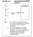
While the capacitor from MCLR to Vss does bypass transients as well, it also serves two additional functions as well.

Reference PIC16F87XA Data Sheet, pg 148, Section 14.4 MCLR & 14.5 Power-on Reset (POR)

MCLR.jpg

The capacitor provides some ESD protection and as a charging RC network controls the rise time of Vdd as detected by MCLR ensuring proper Reset of the device.

Also I should mention, Hi-Tech recommends using the following compiler directive:

#include <htc.h>

Instead of:

#include <pic.h>


I glad you managed to get your design to function as expected.

BigDog
 
Status
Not open for further replies.

Similar threads

Part and Inventory Search

Welcome to EDABoard.com

Sponsor

Back
Top