momo2000
Newbie level 3

- Joined
- Sep 22, 2014
- Messages
- 4
- Helped
- 0
- Reputation
- 0
- Reaction score
- 0
- Trophy points
- 1
- Activity points
- 35
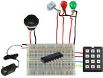
It has been since I was a kid since I built & soldered things, but need to build 5 of these devices for a “simulation” so I’m trying to figure out where to start and am looking for suggestions. I went to the business school, not the engineering school! Is there a project that is somewhat like this that I could modify, do I buy a project book, is it simple enough that someone would give me some direction? Here is what I am trying to build (see uploaded crude diagram of my thinking on the circuit/components):
SUMMARY: Keypad that when you enter the correct 4 digit code (and probably #) it turns the red light OFF and green light ON.
SPECIFICS:
Green light turns on when power applied and is in “ready state/disarmed” (Optionally all lights could be off)
Keypad/IC that can be programmed with a 4 digit code. Code must remain when power fails.
Single push of the momentary switch, “arms” the circuit. Meaning that #1. The red light turns on, and the buzzer sounds for a few seconds.
When you enter the correct 4 digit code, the circuit goes back to “ready state/disarmed” meaning that #1. The red light turns off, and the green light turns on.
Device now back in “ready state”, momentary switch could be pushed and system “armed” again (or in rare occasions, the 4 digit code could be changed).
The 2-light/buzzer combo unit [that I must use] is 24VDC, so not sure if I can run that directly from the board/IC or will have to use a relay. Running directly from the board is MUCH PREFERRED. This 24VDC 2-light/buzzer combo unit is the only part that is already determined. All other parts are flexible.
Need to put the IC/Board/Switch in a project box.
Of course cheap, reliable, and easy for an amateur to build

- - - Updated - - -
OK, been doing more thinking. I have a Arduino Lenardo that I bought a year ago, but never did anything with. Just pulled it out and started with the basic examples. Maybe this would be a good platform for this project? Thoughts or guidance on this strategy of using this board for this project, good/bad idea?
SUMMARY: Keypad that when you enter the correct 4 digit code (and probably #) it turns the red light OFF and green light ON.
SPECIFICS:
Green light turns on when power applied and is in “ready state/disarmed” (Optionally all lights could be off)
Keypad/IC that can be programmed with a 4 digit code. Code must remain when power fails.
Single push of the momentary switch, “arms” the circuit. Meaning that #1. The red light turns on, and the buzzer sounds for a few seconds.
When you enter the correct 4 digit code, the circuit goes back to “ready state/disarmed” meaning that #1. The red light turns off, and the green light turns on.
Device now back in “ready state”, momentary switch could be pushed and system “armed” again (or in rare occasions, the 4 digit code could be changed).
The 2-light/buzzer combo unit [that I must use] is 24VDC, so not sure if I can run that directly from the board/IC or will have to use a relay. Running directly from the board is MUCH PREFERRED. This 24VDC 2-light/buzzer combo unit is the only part that is already determined. All other parts are flexible.
Need to put the IC/Board/Switch in a project box.
Of course cheap, reliable, and easy for an amateur to build

- - - Updated - - -
OK, been doing more thinking. I have a Arduino Lenardo that I bought a year ago, but never did anything with. Just pulled it out and started with the basic examples. Maybe this would be a good platform for this project? Thoughts or guidance on this strategy of using this board for this project, good/bad idea?


