Continue to Site

Welcome to EDAboard.com

Welcome to our site! EDAboard.com is an international Electronics Discussion Forum focused on EDA software, circuits, schematics, books, theory, papers, asic, pld, 8051, DSP, Network, RF, Analog Design, PCB, Service Manuals... and a whole lot more! To participate you need to register. Registration is free. Click here to register now.

[SOLVED] [Moved] 8051 Assembler LCD Programming

Status
Not open for further replies.
Re: Programing In Assembly for 8051

Hi,

4.5V is not 5V.
Why is it not 5.0V?

With Pin2 = 4.5V you should have -0.25V at Pin3. According datasheet.
*****

Without scope it will be hard.

Additionally the circuit is so confusing. It is mixing several periferal access methods. This makes it very difficult.

With every access to one periferal you need to take care about the other periferals connected to the multiplexed data_address bus.
Therfore I recommend to get rid of the "MOVX @DPTR" instruction.
(See microcontroller datasheet page167 "External Data Memory Write Access" timing diagram. This all happens with your single MOVX instruction. Especially Port0 first switches to output the lower address bits, then it outputs the data bits... all within this single instruction. And your circuit is not made for this!)

***
(I don´t know your ASM instructions, so I have to tell in words. You have to write the true code.)

configure instructions: (port setup)

* Port0 as input (databus)
* Port2 as output (address select part 1)
* output data 0xE0 to port2 (disable all reads)
* port1.0 as output (ADC_WR_n)
* output HIGH on port1.0 (disable ADC_WR_n)
* port1.2 as output (LCD_RS)
* output LOW on port1.2 (init to LOW)
* port1.3 as output (LCD_EN)
* output LOW on port1.3 (disable LCD_EN)
* port3.6 as output (SRAM_RW)
* output HIGH on port3.6 (SRAM_WR = read)
* port3.7 as output (SRAM_DS)
* output HIGH on port3.7 (disable SRAM_DS)

... then we go the next step

Klaus

I had a mistake its actually clean 5V on pin 2.
I have deleted the 6000h external memory usage. Now just writting stright to P0 and updating LCD accourdingly.

I made the instructions as below:
Code:
mov P0,#0FFh
mov P2,#0E0h
setb P1.0
clr P1.2
clr P1.3
setb P3.6
setb P3.7
Hopefully its what you wanted me to do.

The full code looks as below:
Code:
EN EQU P1.3 // Enable Pin
RS EQU P1.2 // Register Select

// Setting P0 as Input
mov P0,#0FFh
mov P2,#0E0h
setb P1.0
clr P1.2
clr P1.3
setb P3.6
setb P3.7
// Setting P2 as Output

lcall Reset
// Insure 8 Bit Mode
mov P0, #38h // Function Set
lcall SendCommand
lcall SendCommand
lcall SendCommand

mov P0, #0Eh // Display Control
lcall SendCommand

mov P0, #06h // Entry mode set
lcall SendCommand

mov P0, #01h // Display Control
lcall SendCommand

mov P0, #'M'
lcall SendData

mov P0, #'A'
lcall SendData

mov P0, #'X'
lcall SendData

sjmp $

SendCommand:
clr RS // Setting 0 in RS (0=commands,1=data)
setb EN // Setting 1 in EN (pulse)
NOP
NOP
NOP
NOP
clr EN // Setting 0 in EN (send pulse)
lcall Delay
ret

SendData:
setb RS // Setting 1 in RS (0=commands,1=data)
setb EN // Setting 1 in EN (pulse)
NOP
NOP
NOP
NOP
clr EN // Setting 0 in EN (send pulse)
lcall Delay
ret

Delay: // 100x5 = 5000us = 5 ms
mov R7, #100
D3:	mov R6, #5
djnz R6,$
djnz R7,D3
ret

Reset: // 160x250 = 40000us = 40 ms
mov R7, #160
D4:	mov R6, #250
djnz R6,$
djnz R7,D4
ret

end

Overall the same issues.
 

Re: Programing In Assembly for 8051

Hi,

I don't know what instruction cycle time I have to calculate with, therefore i write the minimum delaytimes.

Code:
SendCommand:
clr RS // Setting 0 in RS (0=commands,1=data)
(Delay 140ns)
setb EN // Setting 1 in EN (pulse)
(Delay 450ns)
clr EN // Setting 0 in EN (send pulse)
(Delay  500ns)
ret

SendData:
setb RS // Setting 1 in RS (0=commands,1=data)
(Delay 140ns)
setb EN // Setting 1 in EN (pulse)
(Delay 450ns)
clr EN // Setting 0 in EN (send pulse)
(Delay  500ns)
ret

You may increase delay times.

Additionally check that on ALL ICs the correct VCC and GND voltage is applied.

Klaus
 

Re: Programing In Assembly for 8051

When initially powered up, the LCD typically requires a minimum delay of 25ms to reset, initialize and be ready to accept commands.

The minimum delay can vary according to several factors, therefore I would recommend an initial delay of 50ms at the start of your code to allow the LCD to initialize properly.

I do not recognize any such delay in the code you thus posted.


BigDog
 
Re: Programing In Assembly for 8051

Hi,

Just to avoid confusion you could rename the delays to
"SDelay" for short delay, about 100us
"MDelay" for medium delay, about 5ms
"LDelay" for long delay, about 50ms
("Reset" is somhow misleading)

***

Place 4 x LDelay immediately after the port setup

InitLCD:
Run the "SendCommand" four times instead of three times.
****
Place a MDelay at the end of the "SendCommand" function, before the ret.
****
Place a SDelay at the end of the "SendData" function, before the ret.

...
Next step..

Klaus
 

Re: Programing In Assembly for 8051

Hi,

@BigDog.
In the "reset" function there is a 40ms delay.

I agree beginning with longer delays may improve the chance for success.

Klaus
 

Re: Programing In Assembly for 8051

Hi,

Init display: 0x3E, 0x3E, 0X3E, 0x3E, 0x14, 0xE0, 0x06, 0x01

Klaus
 

Re: Programing In Assembly for 8051

Now the LCD showing the black bars for maybe a second and then its disappearing and noting is showen afterwards.

Here is the code i made with your guideness:

Code:
EN EQU P1.3 // Enable Pin
RS EQU P1.2 // Register Select

// Setting Ports
mov P0,#0FFh // Setting P0 as Input
mov P2,#0E0h // Setting P2 as Output
setb P1.0
clr P1.2
clr P1.3
setb P3.6
setb P3.7
lcall LDelay
lcall LDelay
lcall LDelay
lcall LDelay

// Insure 8 Bit Mode
mov P0, #3Eh // Function Set
lcall SendCommand
lcall SendCommand
lcall SendCommand
lcall SendCommand

mov P0, #014h // Display Control
lcall SendCommand

mov P0, #0E0h // Entry mode set
lcall SendCommand

mov P0, #06h // Display Control
lcall SendCommand

mov P0, #01h // Clear Display
lcall SendCommand

mov P0, #'M'
lcall SendData

mov P0, #'A'
lcall SendData

mov P0, #'X'
lcall SendData

sjmp $

SendCommand:
clr RS // Setting 0 in RS (0=commands,1=data)
NOP
NOP
setb EN // Setting 1 in EN (pulse)
NOP
NOP
NOP
NOP
NOP
clr EN // Setting 0 in EN (send pulse)
NOP
NOP
NOP
NOP
NOP
NOP
lcall MDelay
ret

SendData:
setb RS // Setting 1 in RS (0=commands,1=data)
NOP
NOP
setb EN // Setting 1 in EN (pulse)
NOP
NOP
NOP
NOP
NOP
clr EN // Setting 0 in EN (send pulse)
NOP
NOP
NOP
NOP
NOP
NOP
lcall SDelay
ret

SDelay: // 10x10 = 100us = 0.1ms
mov R7, #10
D3:	mov R6, #10
djnz R6,$
djnz R7,D3
ret

MDelay: // 100x5 = 5000us = 5 ms
mov R7, #100
D4:	mov R6, #5
djnz R6,$
djnz R7,D4
ret

LDelay: // 200x250 = 50000us = 50 ms
mov R7, #200
D5:	mov R6, #250
djnz R6,$
djnz R7,D5
ret

end
 
Last edited:

Re: Programing In Assembly for 8051

Is there just one line of black bars or two?

Like so?

lcdblackboxes2.jpg

BigDog
 

Re: Programing In Assembly for 8051

Is there just one line of black bars or two?

Like so?

View attachment 128266

BigDog

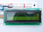
One line like so.
EDIT: decided to picture my own.

I guess its the button line? Or im holding it upsite down.
20160419_035427.jpg

- - - Updated - - -

I would like to metion that I'm actually using KS0066F00 driver which i found out that its the same as HD44780 init, If this was importent to metion to make the LCD to work then here i say it.
 

Re: Programing In Assembly for 8051

A single line of black bars typically indicates an initialization error, which means you are close.

You may have your LCD orientated upside down, while not always the case, the header is typically on the left or top side of the display.

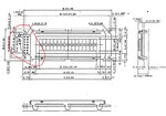
Reference your datasheet:

SEIKO16x2LCD.JPG

The vast majority of these 16x2 LCD displays are based on an HD44780 compatible chipset, apart from a few small time differences, they essentially require the same initialization procedure.

Which is why it is difficult to utilize delays too long, however fairly easy to utilize delays too short. Therefore, the safer technique is to implement and utilize longer than needed delays.

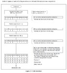
I've attached a clearer HD44780 datasheet with an initialization flowchart, reference page 46.

HD44780Initialization.jpg


BigDog
 

Attachments

  • HD44780.pdf
    322.1 KB · Views: 89

Re: Programing In Assembly for 8051

Hi,

I made a mistake:
Init display:
Init display: 0x3E, 0x3E, 0X3E, 0x3E, 0x14, 0x0E, 0x06, 0x01

Try this. If it doesn't work we have to do some measurements. A lot of single measurements.

***
You are working with 12MHz. In your delay routines it seems you calculate with 10us per "djnz R6,$"
10us at 12MHz are 120 clock cycles. For one single jump instruction. Please confirm this.

***
To prepare your code for the measurements you should place a "stop" just before the initialisation begins.
Code:
mov P0, #3Eh // Function Set
[COLOR="#0000CD"]sjmp $[/COLOR] // stop
Run the code. It's not important what the display show.
Just measure the voltage of all display connections (pin1 ... pin14) and tell us the voltages.

Klaus
 

Re: Programing In Assembly for 8051

Hi,

I made a mistake:
Init display:
Init display: 0x3E, 0x3E, 0X3E, 0x3E, 0x14, 0x0E, 0x06, 0x01

Try this. If it doesn't work we have to do some measurements. A lot of single measurements.

***
You are working with 12MHz. In your delay routines it seems you calculate with 10us per "djnz R6,$"
10us at 12MHz are 120 clock cycles. For one single jump instruction. Please confirm this.

***
To prepare your code for the measurements you should place a "stop" just before the initialisation begins.
Code:
mov P0, #3Eh // Function Set
[COLOR="#0000CD"]sjmp $[/COLOR] // stop
Run the code. It's not important what the display show.
Just measure the voltage of all display connections (pin1 ... pin14) and tell us the voltages.

Klaus

I'm working with 24Mhz. Not 12Mhz. I'll try all you said and edit this reply accordingly.

- - - Updated - - -

Here are the results:

1.VSS - 0.00V
2.VDD - 5.00V
3.VL - 0.25V
4.RS - 0.00V
5.RW - 0.00V
6.EN - 0.00V
7.DB0 - DB7 - 0.00V, P0 All pins - 0.00V
No matter how i change the code there is 0v in all p0 pins all the time...

EDIT:
I found out why this is happening.. its because there are switches connected to P0 and they are all on '0' and then all pins on P0 are '0'.. switched them to '1' and still LCD not working ...
 
Last edited:

Re: Programing In Assembly for 8051

Hi,

7.DB0 - DB7 - 0.00V, P0 All pins - 0.00V
You know you should see 0x3E?
Please confirm that you see 0x3E.

Switches:
Are there any other "surprises" we should know?
You should not switch them to "1". Either high impedance or pullup is allowed.

***
I'm working with 24Mhz. Not 12Mhz.
Even worse. How many (24MHz) cycles does a "djnz R6,$" take?
Re-calculate the values for the delays!
If the delay time is too short (what I expect), then the display won´t work.

Klaus
 

Re: Programing In Assembly for 8051

Hi,


You know you should see 0x3E?
Please confirm that you see 0x3E.

Switches:
Are there any other "surprises" we should know?
You should not switch them to "1". Either high impedance or pullup is allowed.

***

Even worse. How many (24MHz) cycles does a "djnz R6,$" take?
Re-calculate the values for the delays!
If the delay time is too short (what I expect), then the display won´t work.

Klaus

I'm sorry! My teacher didn't told me that switches are effecting Port 0, I don't have schematics of this either. :oops:

Now, all switches '1' and when im sending for example 0x3E its showing :
[00111110]
p0.0=0v
p0.1=4.5-5v
p0.2=4.5-5v
p0.3=4.5-5v
p0.4=4.5-5v
p0.5=4.5-5v
p0.6=0v
p0.7=0v

Yet LCD still have black bars. :|

I don't know how even find how many cycles djnz take, sorry :-?!

Please we are so close! I will thank everyone who helped me, just a little bit more and we solve it.
 

Re: Programing In Assembly for 8051

Hi,

I don't know how even find how many cycles djnz take, sorry !
Please find it out. It´s urgent. For this project for next projects. For now for future.

Please we are so close! I will thank everyone who helped me, just a little bit more and we solve it.
Don´t hurry. Step by step.

Klaus
 

Re: Programing In Assembly for 8051

Hi,


Please find it out. It´s urgent. For this project for next projects. For now for future.


Don´t hurry. Step by step.

Klaus

Ok this is the calculation i made and hopefully its the right ones.

24Mhz
Frequency = 1 / 24Mhz = 0.0416us
Machine cycle = 0.0416us per cycle * 4 cycles (fetch, decode, execute, store) = 0.166us per instruction
Tosc = 6 instructions * 0.166us per instruction = 1us to complete loop
Duty Cycle = 0.166us / 1us * 100 = 16.6%

Is this what you asked me to do?
 

Re: Programing In Assembly for 8051

Hi,

Is this what you asked me to do?
I´m not sure about Tosc and duty cycle...

***
Code:
SDelay: // 10x10 = 100us = 0.1ms
mov R7, #10
D3:	mov R6, #10
djnz R6,$
djnz R7,D3
ret

I try .. but you have to correct me if I´m worng, because I´m not familiar with the used microcontroller.
24MHz (clock)
24MHz / 4 (cycles per instruction clock) = 6MHz (instruction clock).
2 instruction clocks per dnjz = 3MHz => 333ns

333ns x 10 (mov R6, #10) gives 3.33us
3.33us + 166ns ( mov) additionally = 3.5us
3.5us x 10 (mov R7, #10) = 35.0us.
35us + some +verhead = maybe 37us
--> this is far away from the estimated 100us.
Now when we use SDelay and expect it to last 100us but indeed it takes only 35us then the delay is too short for the display. This may cause the display not to work correctely.
The same is with the other delay routines.

Please review my calculations. And correct the delay setup.

Klaus
 

Status
Not open for further replies.

Similar threads

Part and Inventory Search

Welcome to EDABoard.com

Sponsor

Back
Top