Continue to Site

Welcome to EDAboard.com

Welcome to our site! EDAboard.com is an international Electronics Discussion Forum focused on EDA software, circuits, schematics, books, theory, papers, asic, pld, 8051, DSP, Network, RF, Analog Design, PCB, Service Manuals... and a whole lot more! To participate you need to register. Registration is free. Click here to register now.

[SOLVED] Motor-based wind sensor, polarity effect on supply rail?

Status
Not open for further replies.

d123

Advanced Member level 5
Joined
Jun 7, 2015
Messages
2,505
Helped
494
Reputation
992
Reaction score
525
Trophy points
1,393
Location
Spain
Activity points
27,148
Hi,

I'm making a simple wind speed sensor using a 5V DC solar motor (max. 55mA). The op amp for testing is an LM324, but in real circuit will be a rail-to-rail input and output LMC6464 as need to be sure output is over minimum for CD4000 5V logic high signal (3.5V), so LM324 not quite reliable for this (3.5V out max. at +5Vs).

Want to keep whole circuit on single +5V supply for sake of simplicity, and to be able to tie several sensor grounds to same ground as several comparators and a few CD4000 logic gates.

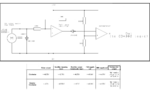
It shouldn't ever happen (like the Titanic), but to be safe in case the wind ever blows the anemometer cups counter-clockwise and creates an inverted polarity signal, there is a full-wave rectifier between the motor and the comparator.

In principle the circuit is working okay, but I have a doubt as to whether when the motor spins counter-clockwise this has any effect on the supply rail or adjacent ICs, despite the DMM readings to the contrary - the whole sensing circuit is that in the schematic along with several other comparators fed from different analog sensors.

In the image there is the schematic, and a small table with measured results from spinning the motor with my fingers, enough to get a reasonable voltage in both directions.

From what I see, the motor counter-clockwise direction and inverted polarity output is having no effect on the supply rails, it seems too good to be true, which is why I'm asking if this circuit is a sound design.

Also, given the difference in voltage between positive input and negative input - Do I need to place a 10K resistor from the non-inverting input to ground, or from motor "ground"/black terminal to ground to balance the signals? Ask because... Not sure if what happens is relevant to electrical issue, or is mechanical and idiosyncratic to this motor: the motor spins far easier CCW than CW, which is reason for asking about need for balancing resistors somewhere in circuit.

Thanks.

- - - Updated - - -

Apologies, it was right under my nose: the diode was causing the voltage difference... Have attached updated schematic with updated DMM readings.

First question still applies: Is this circuit a valid/functionally acceptable design, and when/if motor runs CCW will not have a negative (no pun intended) effect on the supply rail or other parts of the whole circuit, please? Thanks.

Polarity effect question - revised.png
 

Attachments

  • Polarity effect question.png
    Polarity effect question.png
    117.3 KB · Views: 174

rather than worry about Titanic, wonder if the brush motor has more friction in one direction and is intended to be bidirectional, or if the diode is shorting out the motor voltage thus creating a force to make it hard to turn.

The negative voltage input should not have a diode unless it is a Zener to limit the negative voltage or Vin(-) below ground.
Since inverting output cancels negative input, the range of motor speed and its output (negative) voltage must not exceed the supply.

If you want to make the anemometer bi-directional for any reason, use a full bridge rectifier and not a precision half bridge.

Otherwise positive clamp diode and negative zener clamp diode is all that is needed.

What is the V vs wind speed performance?
What is the start wind speed for turning? due to friction....

Why do you only want a comparator instead of an analog voltage?
If just binary wind detect, what wind speed?
Do you think h comparator should have hysteresis.?

These questions should be answered in your "Design Spec" so you should not ask about implementation when we dont know your spec.

So define the input analog and outputs and the process in a simple spec.
Dont worry about LM358, just the specs. THen design becomes obvious.
 
  • Like
Reactions: d123

    d123

    Points: 2
    Helpful Answer Positive Rating
Have you calculated what the motor out put is at what wind speed? With your circuit the two diodes clamp the DC output at .7V so after that voltage being generated the diodes conducting brake the motor. As the gain of the first op amp is 1, the output is limited to .7V at present.
Feed the motor to a 10K pot using the slider and earth as the output to the OP amp. Now arrange that your scaling is .5V out for the maximum wind speed. Set the op amp gain to 10, ignore negative output it won't last very long. The wind speed scaling factor would be wrong any way.
Frank
 
  • Like
Reactions: d123

    d123

    Points: 2
    Helpful Answer Positive Rating
Hi, thanks for input. I present my defense:

It's a bi-directional motor. Adding second diode balanced out that difference, and Chuckey's reply explains ~0.75V in both directions - I can live with that as don't need rail-to-rail in but do need rail-to-rail out, I'll just scale resistor divider for comparator(s) to match. Another sensor only has a max. 1V output, and as voltage drop over distance needed is virtually null, more concerned with clean-ish switching between comparator levels, and not risking going over supply levels.

Prefer motor not to spin too much were there to be a high wind (here it is worse than cold weather for plants and can be very strong indeed - snaps mature tomato plants quickly), so braking will help.

I copied "Figure 53. Full-wave Rectifier with Input Current Protection" from a TI op amp datasheet, I thought that was the same, as the previous application hint schematic is called, "Figure 52. Half-Wave Rectifier with Input Current Protection"; and as the one I'm using appears to fulfil requirements (whether input above or below ground, output is positive) thought it was correct. An anemometer shouldn't blow CCW based on the aerodynamics of the cups, but just in case it did for a second or a few seconds, I want to include this feature, that's all.

As I said in first post (reason: not to waste time actually making the thing if it is bad for the supply rail, as the circuit is big and hard for me anyway, so have to be sensible about time dedicated to each section), have tested motor spinning with fingers, when am satisfied it's okay to use, which apparently it is, then I can proceed with making the anemometer cups somehow and testing with a fan which has a specific airflow, and from there calculate the circumference needed to roughly measure x number of metres per second, and with real world experimentation and measurement discover the start wind speed for turning.

As this is a hobby project, aimed at learning to use op amps a bit better, and National Instruments won't offer me a job for doing this, I am aiming at the precision necessary for a wired logic circuit to maintain a greenhouse to a reasonable degree. I have a Pi type device, and coding would save on a load of components and improve functionality greatly, but learn a lot with analogue circuits.

I want a comparator so that it can trigger CD4000 logic devices (and relays, or whatever is appropriate) to carry out mundane functions like turn on a fan and extractor, open a vent, water, mist, turn on a heater, etc. The comparators make it far simpler to have set levels for "do" or "don't" functions which can be combined with other sensor analog voltage inputs. Toyed with idea of incremental voltages like for fan and heat control, but have opted for comparisons which create "yes or "no" results.

Still getting my head round hysterisis, for example now the four temperature comparators all function correctly (one level goes off and another level goes on and vice versa as intended), bar one which at first had a ,little hysterisis and had to to remove a 3mV glitch between two states - no idea what caused that, but an additional resistor solved the issue, as I understand I don't want to use hysterisis but want clean switching and no IC mulling it over until it's sure which would cause bad combinations. I imagine, as is obvious and from what I've read about greenhouses, that real world experimentation will show where fine tuning will undoubtedly be needed...

Because I'm not an engineer, I've been working on this for about three weeks when time permits, and more time has been learning new things a lot, doing schematics, reasoning out logic functions related to what should happen, sums I find difficult, and very little playing with components. First was the list of objectives, along with a set of real world parameters to follow, what I have and what I need, next doing the sums when needed, then breadboarding to learn how to make a window comparator and translate the output to another comparator for a logic level signal. Since then I've been putting together the comparators and window detectors, and figuring out the wired logic interaction and devices necessary, with my head and minimal experience after a year of self-learning and asking questions here when appropriate.

I have to be honest, Sunny, I admire your incredible ability a lot, I envy your mathematical and electrical skills, but sometimes it may be easy to forget some of us are just little shoe shufflers who play with components at home and barely grasp Ohm's Law, and a hobby is perhaps more a journey of learning (from mistakes and slack design methodology) than being able to write a BOM and oversee a factory production line :). You just have to look at the few of us who post this way to understand this - again: "My circuit does not work (no schematic included), I have read no datasheet, why bother or google for info when I can ask here - after making it."

Seeing that I think I understood there is probably nothing like unexpected surprises (the purpose of my original question) with the circuit as is, even if achieved "the wrong way round", then that is good enough for a little hobby circuit (not a strip light on sale in shops!), and thanks for the suggestions.
 

take care , using a dc motor to sense wind speed might have a nonlinear V/[m/s] dependence. I learnt that in a hard way .. In the end i built an anemometer using ping pong balls and scrap from old PC mouse
anemo.jpg
Principle of operation:
The disk and cup set are rotating on the same axes. Due to the holes on the disk's periphery the fotodiode receives intermittent light from the LED placed on the other side of the disk. Pulsating voltage arises on pin 2 of IC 74AC00, which is a NAND Schmidt Trigger circuit. On output pin 2 of J1A connector a TTL level signal can be collected and its frequency f measured with the PIC mcu.
The wind speed is computed as follows: v = 20 x f [m/s] , where 20 is the wind speed sensor's constant.
Wind Speed sensor Operating range 0.3- 20 [m/s] .
PS: rotation is same because of orientation of cups (pingpong balls cut in 2 ) , anyway does not matter, f will be same

- - - Updated - - -

if you are not using the circuit for measurement , i suggest to use only the dc motor (as generator), and an adjustable shunt rezistor with low voltage coiled reed rellay. (i found reed rellay with coil on it, that worked starting from 1.3V )Than at setup you just have to adjust the rezistor to make the rellay clamp at desired wind speed .
At my experiences with anemometers i used a wind tunnel made up from canalization pipe and adjustable cooling fan
 
Last edited:
  • Like
Reactions: d123

    d123

    Points: 2
    Helpful Answer Positive Rating
@d123 I expect hobbiests to learn from the pros by following fundamentals. Block diagrams, input output specs, functions .

From interpreting your results, you are using CW only which generates a V+ with speed in a linear fashion. Therefore you don't need a rectifier just a negative clamp diode to block V-. Also you were using the wrong polarity input to the precision half-wave rectifier since your +input cannot drive the output below the V- rail.

RULE
Anytime the inputs to an Op Amp are not equal, the output will saturate like a comparator ( except for minor Vio offsets in mV) so if Vin(+)>Vin(-) then Vout to max + towards Vcc and if Vin(+)<Vin(-) then Vout goes to V- rail or GND in your case;

This is true in every application. Linear mode only exists when Vin difference ~0V, whether biased at V+/2 or Vin(-)or(+) referenced to Gnd.

HYSTERESIS
This is easy.
Linear forward gain is based on feedback ratio to V(-) in. Rf/Rin=Av
% Hysteresis is % feedback with infinite gain (>1e6)
Rf/Rin= 1 / %Hysteresis
or Rin/Rf = % Hysteresis ( input deadband as a % of output swing)
Since input always has noise, if after filtering you know noise level inVpp the choose Rin/Rf to be at least twice for margin of input noise this is like saying SNR=2 in decision. The threshold shifts above and below bias threshold by half of this %.

A CMOS 40xx Schmitt trigger has ~ 50% hysteresis. from 1/3 to 2/3 Vcc. so it can tolerate much higher noise input than say 2% hysteresis, but then thresholds are closer than 2%.

A home thermostat has about 0.5'C hysteresis for example. Some are worse at 1'C others better at 0.25 'C but cycles more often.

So it depends on desired result and action between noise rejection and tight regulation and frequency of cycling motor.

If you wanted to maintain air flow speed with wind and fan when no wind, then this is possible using linear feedback and no hysteresis.
But that means you need to define it ( ie. spec.)
 
  • Like
Reactions: d123

    d123

    Points: 2
    Helpful Answer Positive Rating
Don't you see that your rectifier is half-wave, not full-wave?
Don't you understand that the output from a DC motor that is spinning is a DC voltage, not an AC frequency? Then there is no way your circuit can measure wind speed. It can simply say wind is blowing or wind is not blowing.

What limits the output current from the motor to only 55mA? When the wind blows very hard then the motor output current might be high enough to burn the motor and/or the protection diodes.
The input of your opamp is inverting with a low resistance. Why not make it non-inverting with a very high resistance then a series resistor can be added between the motor and the electronics?

Why is the reference voltage from the voltage divider feeding the comparator so high at almost 4V? The output from the rectifier will never get anywhere near 4V then the output of the comparator will always be as high as it can go. Also most comparators have inputs that do not work with voltages so close to their positive supply voltage.
 

Hi,

Lots of helpful information and explanations, thanks. I wanted to use a reed switch and a magnet for the wind speed "tachometer" so tried two frequency-to-voltage circuits (one by an Analog Devices engineer for a 1kHz version), but one was for an inductor-based frequency input and 'though it worked quite well seemed to inject frequency back into the input signal (a 555 go get 1, 10 and 100Hz), and the second was beyond my comprehension, frankly - just got 5V at 1Hz and 800mV at 100Hz (and wasn't willing to look for signal level inverting add-on block), so not a good way of representing incremental wind speed!

"Don't you see that your rectifier is half-wave, not full-wave?" - obviously not, I never use op amps, and the datasheet describes the circuit as "Full-wave rectifier". I'll have to re-read electronics tutorials.com or whatever the web is called about full and half wave, thanks.
Sorry, Audioguru, the schematic was simplified to give the main idea (only one comparator level, randomly picked, also resistor divider trigger level), more interested in opinions about the ful...half-wave rectifier and motor set-up, the comparators work fine. Seemed unnecessary/unhelpful to show two comparators and a window detector to ask about a motor into a rectifier into a comparator. btw - I have run out of "helped me" votes, so can't click on your post today...tomorrow, thank you.

"The input of your opamp is inverting with a low resistance. Why not make it non-inverting with a very high resistance then a series resistor can be added between the motor and the electronics?" - I'll have a look at that, thanks.

With preliminary finger spinning approach, light spin gets about 200mV, firm spin gets about 750mV, so it looks linear enough to see: <30%, 30 - 60%, and >60%. Datasheet said 55mA max., so hope to scale circumference/diameter (however you prefer to think of it) of cups and base plate to avoid this happening. Testing with the fan will tell me if the motor may burn or not in high winds. I hope not as the frequency-to-voltage method will complicate things more than I want.

"A home thermostat has about 0.5'C hysteresis for example. Some are worse at 1'C others better at 0.25 'C but cycles more often." - this concerns me, but the alternative is not good: two conflicting outputs high at the same time is a "forbidden State" or including a little dead zone where nothing will happen (equally not good) or having a "wacky" machine clicking things on and off all day (and being wasteful in the process? Presumably the latter is the least of the evils so things happen when they should and not when they shouldn't or not at all for a while. - Why do people use PICs or Arduinos instead nowadays (sleep command, etc.)?!

Will digest information provided and see misunderstood half of what you guys have just said then be able to assimilate your very helpful knowledge in a useful way, thanks.
 

I see lots of conceptual problems:

1. the back to back diodes will virtually short out the motor after it reaches a few RPM. As an experiment, turn the motor by hand with it disconnected then short it out and feel the difference in resistance to being turned.

2. I can't see why a 'solar motor', assuming this is one intended to be driven from a small PV panel, would be bi-directional. They normally use leaf brushes on the 'drag' side of the commutator (rotating toward the open end of the brush) and although they will work in reverse, it would likely wear the brushes very quickly.

3. The motor will be intended for DC operation and will work as a DC generator when rotated. That rather makes the whole issue of rectifiers a non-starter. Admittedly, there will be some speed related 'noise' from it but I wouldn't consider that a good indication of the speed, more of the quality of the brushes and their contact points.

To make it work as an anemometer, I would do it this way: Do wire one diode across the motor so it is harder to turn in reverse. Obviously make sure the mechanical side of things is biased so it only rotates in one direction as well. Then apply a resistive load across it (~100 Ohms?) to give it something to push against, this will help to linearize it's output and also give a degree of braking so the mometum of the vanes plays a smaller part in the measurement. Across that I would use an RC filter to reduce noise. The result should be a DC voltage ranging from 0V to whatever the motor's top output is. Measure the voltage to determine the speed.

Brian.
 
  • Like
Reactions: d123

    d123

    Points: 2
    Helpful Answer Positive Rating
For any given rotor, the best transducer for converting the rotation into pulses is a rotating disc with holes in it to stop/allow a light beam to be detected by a photo cell, because it imposes no load on the rotating parts. The other advantage is that you can drill, say, 60 holes in a diameter of 50mm, so get 60 pulses per revolution. This method is also good for high speed, limited to say, 60,000 RPM by the speed of the electronics and has intrinsically excellent linearity.
Have you built your rotor yet, this is the difficult bit, making it weather proof and run freely. The electronics are easy.
Frank
 
  • Like
Reactions: d123

    d123

    Points: 2
    Helpful Answer Positive Rating
"lots of conceptual" errors too. Glad I asked original question...

Idea of full-wave rectifier (to convert not AC signal, but reverse polarity DC signal if need be) was that if anemometer turned in "wrong direction" (mechanically improbable if understand cups on anemometer correctly), wouldn't damage electronics - I now see this is pretty pointless and superfluous.

Back-to-back diodes...oh dear, tried the motor as Brian said, open and shorted, and understand.

Seems I have little idea of the motors I have.

Gets better: This reminds me of the "quick" power supply for another circuit that took months, I don't want that experience again - objective is logic and op amps, not an eternal problems anemometer just to avoid buying one for a little hobby project. Sunny often says about starting with clear specs, I didn't check top wind speed here, and assumed maybe 80kph, it's actually ~160kph. Doing sums, it seems need a 50mm circumference to cover this safely to 180kph, and then I get 36m/h = 1mV. Still have a lot of sums to do, even if only want to know "no wind > weak breeze", "weak breeze > good plant growing wind speed" and "too strong a wind" in volts. No clear specs with this part, indeed.
Based on this, will change to a motor sold as bi-directional that can operate up to about 9V, and as advised use the 5.1V Zener I have to clip/limit in strong winds; checked rps with reed switch and magnet (very hit and miss measurement using a DMM with frequency counter, maybe reed not able to keep up?) and got ~1000rps at 10cm diameter (31.4cm circumference).

Dohhh, right, chuckey: I'm slow, trying to measure 1Hz when common sense is to measure at least 60, as you said..., thanks. Haven't got to cups and rotor yet, know it will be hard to get right so leaving that DIY homework as long as possible, want the circuit correct first before getting stuck with mechanical problems I see looming - including the relative humidity sensor, which seem equally fussy to implement in other ways (avoid direct light, not sopping wet, and so on).

The reed relay idea seems good, but I don't have one, and am trying to avoid getting more things than I can justify to myself, already had to go over-budget with better op amps and a couple of logic gates, and the humidity sensor - not happy about this, am sick of making up for lack of skills and knowledge by buying "yet another component" (half the time unnecessary as well).
Like the ping pong ball idea, thanks, wanted to use coffee measuring conical plastic spoons, but have none, so will go with the balls.

From all your suggestions and explanations, much appreciated, has helped to see a lot of clumsy mistakes/errors so far with this - no surprises there, I'm going to try what Brian has suggested combined with the Zener and see how it goes.

Thank you.
 

So i get it right , you don't want to measure wind speed in [m/s] , you just want a circuit that triggers at a certain wind speed ?
if so you complicated to much with op amps. What if you replace reed relay with 1 tranzistor ?
d123.jpg
Those values could be for start , there are a lot of electronists around here who can tell exactly what values should be . I would prefer testing out in real life...

I also believe that NPN tranzistor vould give inverted output, and a PNP trnzistor would give non inverted output, just that in that case it would be an emiter follower circuit . (usually we place load -rezistor or led or whatever- in collector )

- - - Updated - - -

PS : about the pingpongs , i used a silicone bar that i found to fix them . I melted the silicone with soldering gun. The whole thing was made from scrap . I found an old videorecorder that i savaged , i took the smallest bearing (5mm dia.)and housing from there. That had also a 2 mm ax in it, which had a cooper (or bronze) pulley in one end . I soldered 3 pieces of cooper wire to that . The wires where about 10 cm long . At their other and i bent little circles to fix the half ping pong balls with the melted silicone . The other end of the 2mm ax was free so that's where i fixed the opto-barrier disc from an old mouse.
To make the body of the whole thing i used a piece of plastic pipe which had 5mm thick walls (from water installation , don't know in English, there are components to join 3/4 pvc pipes ). The thick walls allow ti fix caps with 3mm screw
That was in 2011, it still works now .

In similar way i used a stepper motor connected as generator to detect 5 m/min speed at a sorter machine in factory. I used the stepper , a bridge rectifier and an 5v dc rellay . I was lucky that the rellay clamped at 5m/min speed from the first time ... that was pure luck .
 
Last edited:

Cheap radio controlled model airplanes use a small DC motor used to open and close a CD tray and to vibrate a phone. Their brushes wear out soon when running for an hour or two.
I think the cheap solar motor will also wear out soon, maybe in the first day of running in the windmill. The motors in some airplanes stop when their bearings wear out.

I think a parallel zener diode will protect the bearings in very strong winds but the high current in the zener diode might burn it and the motor.

Sunny, I think a solar motor turns backwards when the sync pulses from the sun are "blacker than black".
 
  • Like
Reactions: d123

    d123

    Points: 2
    Helpful Answer Positive Rating
Hi,

Fair enough, motor's a poor concept, especially re wear and tear.

I was looking at the Zener datasheet I have, and if understood IZk correctly it says min. 1mA to regulate, graph of regulation versus current makes it look more like 100uA keeps it around 5.1V, but still..., counting on over-voltage to comparator (input range can withstand 300mV over supply rail of +5V) being from 5.2V up to 9, or for arguments sake, 12V, then according to OnSemi Zener theory and design app note, assuming op amp as load is pretty much 0 mA current, then would expect from 4 - 7mA in Zener in overvoltage situations using 1K series resistor for Zener, if use 100 ohm then gets bad - ~40 - 70mA. Presumably my calculations are wrong as main idea I have about Zeners is that they waste a lot of energy doing their work - that doesn't fit in with ~7mA. The other motor should handle some current, but have no datasheet for it, and guessing is if wishes were horses territory.

Anyway, I agree, the more I re-read (past tense) this thread earlier, and finally comprehended things said yesterday and earlier today, have inclination to try frequency-to-voltage circuit again after understanding Frank's 60 holes in the plate for frequency, etc., as if I could get it to work it presents far fewer issues and problems than using either motor.

One day I'll learn that quick-fix circuit solutions never work, because wishes aren't horses.
 

It depends on your ultimate needs, are you looking for something to measure the speed or just let you know when a threshold speed has been reached?

I would stay away from reed switch solutions, the switch operates at least once per revolution and despite them being extremely reliable, they do have a finite lifetime. Optical should work almost forever since there are no moving parts in the sensor, their drawback is needing a continuous supply for the light source although that might only be a few mA. If you don't need precision RPM figures, you can use a slotted switch with a tab passing through the slot or a reflective opto-switch with a mirror surface on the rotating parts.

For speed measurement, just count the number of pulses in a given time frame, if you need an 'over speed' switch, you can easily do it with a timer, counter and numeric comparator or with a pre-loaded counter that counts up/down to zero at each pulse form the opto. If you want to be clever (danger!) you can use two sensors in quadrature and it will not only tell you how fast it rotates but which direction too. It's an ideal job for a small microcontroller (PIC10 series perhaps) if you want to delve into programming.

Brian.
 

Hehe, i love to see how you guys complicate simple things .... of course it will work, for a while. Anything works , for a while . Even a brand new anemometer will work only for a while. The thing is what do you expect or what is needed .
That little generator will supply whatever circuit you connect , it will not damage by current even if connected to shortcircuit load . Wind will never spin it with 750 ....1000 rpm or whatever it's nominal speed is. Actually brushes-collectors will oxidate because of moisture in open air . Current will never kill a dc brushed motor used as generator, since it was not designed as generator ...
Don't let yourself down , do it anyway :) (just to show clever people that it can be made ! :) )
Most guys here have fancy programs that can simulate circuits , that's how they say about component values or types so quick . Those programs are based on datasheets , practice can say something else . Actually i saw mathematician who never saw a microcontroller genereateing a working code in C (Matlab can generate code for PIC's now days :) )

PS: i experienced the whole thing will rotate in one sense because of the cups , whatever wind direction is .
 
Last edited:

Hi,

Thanks, Reed switch: I know, did the sums and saw would last about 3 days! Just used it for quick frequency count yesterday. Have IR barrier IR LED and photodiode that could use instead, if can implement Frank's suggestion of multiple holes in disk.

The "problem" here Brian, is that one objective I set myself for this project (despite looking at the Armadillo I have and mulling over struggling with elseifs and "syntax error" in Python code) is no programmed devices, only analogue circuit, cabled logic like back in the days before people had access to PICs and arduinos, etc. Even replaced a few OR gates in schematic with diodes for this reason.

Bit of a quandary, frankly, as time is a valuable commodity, and seem to waste far too much already... The motor as zsolt1 says, seems viable, especially for a home-baked project.

Alternatively, and as a back-up plan, could some-one look at these schematics, and say if there is in principle no reason or some reason why I could not use either circuit for a frequency-to-voltage converter, please? I tried both and had respectively no and little success - I think first as tried with only 1 - 100Hz, and second was injecting a much higher frequency back (!?) into astable 555 at 1 - 100hZ. Tried the first with 5.1 Zeners.

These schematics are taken from the following webs:

**broken link removed**

https://mathscinotes.com/2014/03/a-simple-frequency-to-voltage-converter/

Probably important is that author of second says in preamble: "...a small sensor interface that converts the inductance of a sensor to a digital signal with a frequency that is related to the inductance value."

simple f-to-v converter.JPG1kHz f-to-v.JPG

Thanks.
 

No doubt the motor will work but a DC motor to measure wind speed will be harder than you think. It has nothing to do with brushes burning out due to the generator current and a lot to do with the risk of damaging them by reverse rotation and geneal wear and tear. At it's simplest, you use a motor and nothing else, in theory, the voltage it produces will be proportional to its rotation speed but in practice you will see other effects due to brush bounce, inductance of the coils, and even internal interference supressors in some cases. I searched data sheets for small DC motors, including some very expensive ones and no manufacturer specifies expected life in terms of rotation, I would expect 'hobby' motors such as foud in PV appliances, DVD players and toys to last maybe 500 - 1,000 hours in continuous use, that means only 6 weeks in the wind. A few years ago I worked on the design of a precision very high speed motor and we anticipated 500 hours before the commutator wore out. An optical system presents no drag on the anemometer and the sensor has no moving parts to wear out.

The methods you listed will all work to convert frequency to voltage. Remember that if you use an optical sensor, you can choose how many pulses per revolution you want. Each method has advantages and disadvantages, a PLL will have limited measurement range but a linear output, additionally, it may give an unpredictable output when out of range. The pulse counting "charge pump" method is fairly linear but the output is modulated with peaks from the sensor so you have to be careful if you feed it to a comparator. The most accurate is to use a digital frequency counter and ADC, it's not as complicated as it sounds, a timer (555 possibly) a binary counter and an op-amp with an R-2R resistor network will do it. Alteratively, you might be able to get a dedicated F-V converter IC, in days of old the LM2917 tachometer was commonly used but I'm not sure if it's still available. The data sheet is worth reading for ideas.

Brian.
 
  • Like
Reactions: d123

    d123

    Points: 2
    Helpful Answer Positive Rating
Status
Not open for further replies.

Part and Inventory Search

Welcome to EDABoard.com

Sponsor

Back
Top