yassin.kraouch
Advanced Member level 2
Hi,
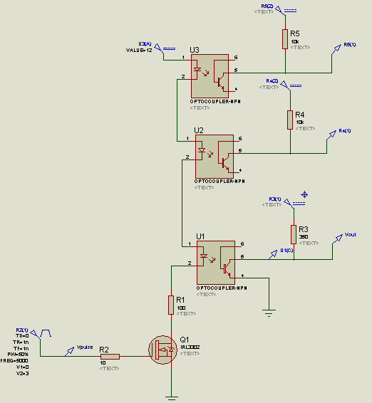
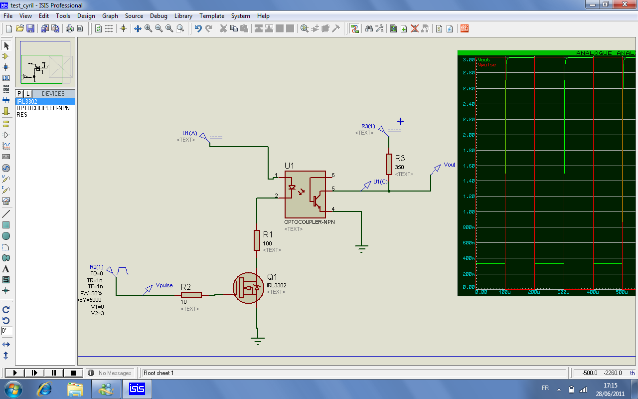
the Vout of my circuit is between 300 mV and 3V, i would like that my Vout is between 0 and 3V, how can i do this ?? please help!!!
best regards
the Vout of my circuit is between 300 mV and 3V, i would like that my Vout is between 0 and 3V, how can i do this ?? please help!!!
best regards