abuhafss
Full Member level 2

- Joined
- Aug 8, 2010
- Messages
- 142
- Helped
- 1
- Reputation
- 2
- Reaction score
- 0
- Trophy points
- 1,296
- Activity points
- 2,383
Follow along with the video below to see how to install our site as a web app on your home screen.
Note: This feature may not be available in some browsers.

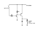
So if I am reading the circuit right, you are trying to use a NMOS transistor to turn on an inductive load. You are using a npn transistor to drive the MOSFET gate on and off. So what happens is when the switch is off the npn is off and the NMOS is power on. When the ignition switch is on, the gate is grounded and the switch is off. So are you measuring the simulation on the correct switch condition where the NMOS is on? I also did notice that it you have the nmos hooked up backwards that what is usually done. Usually you have the NMOS as a low side switch where your load is connected to power and the NMOS completes the circuit to ground. So you may have a polarity issue here. The way you have the circuit hooked up you would need a charge pump to turn on the NMOS.
Ah you're right, sorry not the greatest eyes. So PMOS makes a lot more sense, are you sure that it is hooked up correctly still to get it to turn on? I am not sure on Falstad if it matter or not.


why the transistor need to be such big 2N3055 (10A)? Can't 2N3904 do the job?
For operating a solenoid there's no need for high speed so you can make the collector (gate) resistor 1kΩ and the base resistor 10kΩ for the NPN transistor. The collector current is thus only 12mA and just about any NPN can be used.I tried the configuration with IRF4905 (74A, R-ds 0.02Ohms), 2N3904, 100R/2W and 271K varistor (in place of diode) on a three-wheeler. It worked but, I think the 271K varistor could not protect the mosfet. The actual load is about 0.4 Ohms. The gate resistor draws about 130mA and the base resistor draws about 120mA so, BC54* family cannot be used which can handle only 100mA.
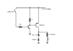
Crutshow>>> I want to use it in place of starter relay to power-up starter solenoid.
For operating a solenoid there's no need for high speed so you can make the collector (gate) resistor 1kΩ and the base resistor 10kΩ for the NPN transistor. The collector current is thus only 12mA and just about any NPN can be used.
Stay with the diode across the solenoid for transient protection but you may want to add about a 30V 1W zener in inverse series with the diode to reduce the turn-off time of the solenoid and minimize contact arcing.
I think you burnt out the base-emitter junction of your 2N3904 transistor with a base current that is much too high. For the load of 120mA, the base current should be 12mA for it to turn on well and the resistor value should be (12V - 0.7V)/12mA= about 1k ohms, not 47 ohms which produced a base current as high as (12V - 1.0V)/47 ohms= 234mA!! (If the input signal source can supply that much current at 12V.)

Yes, that is what I was suggesting. The 1N4007 should be fine. But upon further though I realize that a 1W zener will not tolerate a 20A pulse. You will need a 10W zener or a 30V transorb for that. Alternately you could put a 1.5 ohm resistor in series with the diode, in place of the zener, to reduce the solenoid turn-off time.Is this what you are purposing? Is 1N4007 OK or some high rated ampere?
Yes, that is what I was suggesting. The 1N4007 should be fine. But upon further though I realize that a 1W zener will not tolerate a 20A pulse. You will need a 10W zener or a 30V transorb for that. Alternately you could put a 1.5 ohm resistor in series with the diode, in place of the zener, to reduce the solenoid turn-off time.