d123
Advanced Member level 5
Hi,
Success!
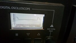
I'm really pleased to say that yesterday I had my first experience of hearing some X7R MLCC 1206 capacitors making that irritating, high-pitched whine/squealing noise ('singing' is not the adjective I'd use for that sound) on a very simple 10 kHz, 10% duty cycle LED driver circuit I had just finished making for yet another torch variant (bicycle light). ...To experience it is more meaningful for me than often reading about - and therefore, abstractly understanding - it, in this case.
I solved it by reluctantly changing Fosc to ~20 kHz, the piezoelectric effect is no longer audible, to human me, at least.
On looking for solutions I read these articles:
Reduce acoustic noise from capacitors
How to reduce acoustic noise of MLCCs in power applications
Capacitors piezoelectric effect
I see that choices are:
1) Make Fosc > 20 kHz
2) Use two capacitors that are half the value of required capacitance value on either side of the board (assuming you have a double-sided PCB) to cancel out each other's flexing, instead of one on one side.
3) Make cut-outs at the ends of each capacitor.
4) Use one of the three types of 'anti-noise' capacitors available. (...$$$!)
5) Avoid using X7R at frequencies in the audible range.
Has anyone tried #3? Is it effective?
Are there any other methods not mentioned in the articles?
I know it's an ignorant question, but all the same, I'd like to know why, if compatible with the design, using either:
a) an RC, or preferably just a C, that is the same frequency as Fosc between Fosc source and offending MLCCs
OR
b) A large value capacitor between Fosc source and the singing capacitors to swamp out the ripple voltage
are evidently not methods that could work?
The frequency makes the capacitor plates vibrate, so why wouldn't swamping with a large value capacitor (relative to Fosc) act like a low pass filter and stop Fosc disturbing the MLCCs?
Is it the board/signal path, or only the MLCC capacitor that causes the vibration?
What I read all said that the capacitor vibrates, so then the PCB does too and acts as a loudspeaker for the capacitor's piezoelectric effect.
Thanks.
Success!
I'm really pleased to say that yesterday I had my first experience of hearing some X7R MLCC 1206 capacitors making that irritating, high-pitched whine/squealing noise ('singing' is not the adjective I'd use for that sound) on a very simple 10 kHz, 10% duty cycle LED driver circuit I had just finished making for yet another torch variant (bicycle light). ...To experience it is more meaningful for me than often reading about - and therefore, abstractly understanding - it, in this case.
I solved it by reluctantly changing Fosc to ~20 kHz, the piezoelectric effect is no longer audible, to human me, at least.
On looking for solutions I read these articles:
Reduce acoustic noise from capacitors
How to reduce acoustic noise of MLCCs in power applications
Capacitors piezoelectric effect
I see that choices are:
1) Make Fosc > 20 kHz
2) Use two capacitors that are half the value of required capacitance value on either side of the board (assuming you have a double-sided PCB) to cancel out each other's flexing, instead of one on one side.
3) Make cut-outs at the ends of each capacitor.
4) Use one of the three types of 'anti-noise' capacitors available. (...$$$!
)5) Avoid using X7R at frequencies in the audible range.
Has anyone tried #3? Is it effective?
Are there any other methods not mentioned in the articles?
I know it's an ignorant question, but all the same, I'd like to know why, if compatible with the design, using either:
a) an RC, or preferably just a C, that is the same frequency as Fosc between Fosc source and offending MLCCs
OR
b) A large value capacitor between Fosc source and the singing capacitors to swamp out the ripple voltage
are evidently not methods that could work?
The frequency makes the capacitor plates vibrate, so why wouldn't swamping with a large value capacitor (relative to Fosc) act like a low pass filter and stop Fosc disturbing the MLCCs?
Is it the board/signal path, or only the MLCC capacitor that causes the vibration?
What I read all said that the capacitor vibrates, so then the PCB does too and acts as a loudspeaker for the capacitor's piezoelectric effect.
Thanks.