Continue to Site

Welcome to EDAboard.com

Welcome to our site! EDAboard.com is an international Electronics Discussion Forum focused on EDA software, circuits, schematics, books, theory, papers, asic, pld, 8051, DSP, Network, RF, Analog Design, PCB, Service Manuals... and a whole lot more! To participate you need to register. Registration is free. Click here to register now.

MiniAmp Replacement. Mono Audio Amp. Gain = 20

Status
Not open for further replies.

cmh2001

Newbie level 5
Joined
Nov 8, 2014
Messages
10
Helped
0
Reputation
0
Reaction score
0
Trophy points
1
Location
Oklahoma
Activity points
73
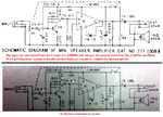
My business uses the Radio Shack mono Mini-Amplifier, part 277-1008. This item is an integral part for a certain sensor that we use. Since Radio Shack may not be around forever, I need to find a replacement for this unit.

I'm considering making my own. Does anyone know of a similar circuit that would give me the same output? We feed the output into a car stereo audio auxillery input.
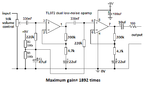
 

The amplifier is designed to drive an 8 ohm speaker but it can drive another amplifier if you want.
Since its rated output is 200mW then its output voltage is 1.26V RMS at low distortion.
Since its rated input level is only 1mV then its maximum gain is 1,260 times which is a lot more than only 20 times.
A dual audio low noise opamp can replace it, each with a gain of 35 times.

Can you point me in the direction of an example circuit?
 

The schematic of the mini-amplifier is shown in a search for it in Google.

I was mistaken, its speaker is 16 ohms, its output level is 1.8V RMS and its gain is 1800 times. A dual opamp with each opamp having a gain of 43 times will work the same but with much less noise and distortion.
A dual audio low noise opamp amplifier with enough gain is easy to design. Can you use a 9V battery or 9V to 12V power supply to power it?
 

The amplifier is to generate an audio signal from a geophone (geospace 20DX specs attached).

Geophone to the mini-amp, to either headphones or aux input of truck stereo. So ground movement becomes audible.
 

Attachments

  • 20DX Geophone Specs.pdf
    1.3 MB · Views: 197

The geophone has its maximum output at the very low frequency of 10Hz.
But the Radio Shack mini-amplifier sales sheet says it cuts frequencies below 100Hz.

I found a correct schematic in Google (many schematics of it were wrong) and most of its capacitors pass very low frequencies except the output capacitor. Since you use it to feed another amplifier and not a speaker then its output capacitor will also pass the very low frequencies.

Here is a preamp that will feed an amplifier. It cannot feed headphones.
 

Attachments

  • high gain, low frequency preamplifier.png
    high gain, low frequency preamplifier.png
    10.2 KB · Views: 195
  • Like
Reactions: cmh2001

    cmh2001

    Points: 2
    Helpful Answer Positive Rating
I found a correct schematic in Google (many schematics of it were wrong).

Here is a preamp that will feed an amplifier. It cannot feed headphones.

I have a few versions of the radio shack schematic. Can you send me a link to the 'correct' one?

The pre-amp that you suggested, how could it be used to drive headphones, if needed?
 

Yes Audioguru, just checked the -3dB points of the .33 MF/220K ~ 25 HZ, and you have two of them. 1MF would be better :) Also depending on the "loudspeaker" 100MF is even lower, could be 2000 MF!
Frank
I calculate 0.33uF and 220k (0.22M) giving a cutoff frequency of 2.2Hz!
1/(2 X pi x 0.33uF x 0.22M ohms)= 2.2Hz.

Also the same from this online RC calculator:

- - - Updated - - -

Here is a wrong schematic and a correct schematic of the Radio Shack Mini-Amplifier:
 

Attachments

  • RC calculator.png
    RC calculator.png
    8.9 KB · Views: 123
  • Radio Shack Mini-amplifier schematics.png
    Radio Shack Mini-amplifier schematics.png
    293.5 KB · Views: 578

Here is a preamp that will feed an amplifier. It cannot feed headphones.

So that I understand this circuit:

1. The 330nF and the 220k resistor set the frequency range from 0 to 25Hz.
2. The 9V, two 100K resistors, an 220k resistor going into the (+) inputs provides a DC offset for the output signal?
3. The 200k resistor and the 4.7k resistor sets the gain of each amp to 1+200k/4.7k = 43.
4. The 10uF on the output of pin 7 blocks DC from going to the next stage. What does the 100 ohm resistor do here?
5. You have the gain at 1892, isn't it just 43 x 43 = 1849?

If the input signal is at a maximum of 10Hz and the normal audible frequency range starts at 20 Hz, will this signal be audible after the next amplifier stage?
 

10Hz was probably never audible and the original amplifier wouldn't have worked at it anyway. The Geophone specs show it's natural resonant frequency is about 10Hz but it's response is relatively flat up to 400Hz, it's those frequencies you would hear in a loudspeaker/headphones.

If you really only want frequencies below 10Hz you should add an active LPF with cut-off just above 10Hz. The amplifiers should be treated as DC gain blocks.

Brian.
 

So that I understand this circuit:

1. The 330nF and the 220k resistor set the frequency range from 0 to 25Hz.
No.
They cut 2.2Hz to 0.707 times (-3dB) and cut lower frequencies at 0.5 times (-6dB) per octave. Frequencies above about 9Hz are passed and have a flat frequency response up to about 30kHz.

2. The 9V, two 100K resistors, an 220k resistor going into the (+) inputs provides a DC offset for the output signal?
They bias the inputs and output of thye opamp at half the 9V supply so the output can swing up and down equally.

3. The 200k resistor and the 4.7k resistor sets the gain of each amp to 1+200k/4.7k = 43.
Almost. 43.55319149 times is correct that I rounded off to 43.5 times.

4. The 10uF on the output of pin 7 blocks DC from going to the next stage. What does the 100 ohm resistor do here?
Yes the 10uF capacitor blocks DC from going to the next stage.
The 100 ohm resistor isolates the opamp's output from the capacitance of a shielded audio cable. If the cable's capacitance is connected directly to the output of the opamp then it will cause phase shift which might cause the opamp to oscillate at a high frequency.

5. You have the gain at 1892, isn't it just 43 x 43 = 1849?
I rounded it off to 43.5 x 43.5= 1892 times.

6. If the input signal is at a maximum of 10Hz and the normal audible frequency range starts at 20 Hz, will this signal be audible after the next amplifier stage?
We cannot hear sounds below 20Hz. They can be felt as vibrations. Many headphones cannot play frequencies below 30Hz.
 
  • Like
Reactions: cmh2001

    cmh2001

    Points: 2
    Helpful Answer Positive Rating
Here is a preamp that will feed an amplifier. It cannot feed headphones.

What makes this circuit unable to drive headphones? Can this circuit be modified to use headphones?

With the Radio Shack amp, we could use either headphones or the line in to the truck Aux input. The Aux input are made to take the headphone output of MP3 players.
 

An opamp has low maximum output current. Some opamps can drive headphones that have an impedance of 600 ohms.
The Radio Shack mini-amp uses an LM386 which is a power amplifier designed to drive a speaker or low impedance headphones with a current that can be fairly high.
 

An opamp has low maximum output current. Some opamps can drive headphones that have an impedance of 600 ohms.
The Radio Shack mini-amp uses an LM386 which is a power amplifier designed to drive a speaker or low impedance headphones with a current that can be fairly high.

So a better replacement for the RS mini-van for this application would likely be the RS circuit with maybe some filtering for the low input frequency.

I've heard that the LM386 is an outdated component. Is there a more modern replacement?
 

Texas Instruments have some modern small amplifiers. National Semiconductor also has some and recently Texas Instruments bought National Semiconductor.
The old LM386 is still produced and works fairly well. Other old small amplifier ICs are not made anymore.

The mini-amplifier circuit worked fine for you so why do you want to add a filter?
 

The RS amp has worked well the last 25 years but it is subject to interference from cell phones, or 60hz power lines, or sometimes you will pick up distant radio swig all in the background.
 

The RS amp has worked well the last 25 years but it is subject to interference from cell phones, or 60hz power lines, or sometimes you will pick up distant radio swig all in the background.
ANY amplifier picks up interference if it is not designed to reject interference. The input wires should be shielded so that they are not antennas. A capacitor at the input to 0V that passes audio but shorts radio signals is needed.
 

Status
Not open for further replies.

Similar threads

Part and Inventory Search

Welcome to EDABoard.com

Sponsor

Back
Top