Rahman.Imran
Newbie level 3
Hi,
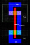
I designed a layout of an Inverter in Microwind2 using 0.12um foundry [CMOS 0.12um - 6 Metal (1.20V, 3.30V)].
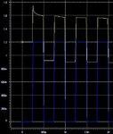
I wanted to do a post layout simulation in HSPICE_Z-2007.03. So from Microwind I got the SPICE Netlist and saved it as *.sp file for HSPICE input. I also added the line ".OPTIONS LIST NODE POST" in the netlist. Then I simulated the *.sp file in HSPICE and observed the graphs from Avanwaves. The input and output curve doesn't match with the curve of an inverter. {The Output is greater than the input. I attached the curve here}
I can't figure out the problem. What is wrong with it?
# The layout is correct. Microwind2 simulation shows curves of perfect Inverter.
# From Microwind2 I generated the Netlist for both MOS Models Empirical Level 3 and Advanced BSIM4, none of them works.
I designed a layout of an Inverter in Microwind2 using 0.12um foundry [CMOS 0.12um - 6 Metal (1.20V, 3.30V)].
I wanted to do a post layout simulation in HSPICE_Z-2007.03. So from Microwind I got the SPICE Netlist and saved it as *.sp file for HSPICE input. I also added the line ".OPTIONS LIST NODE POST" in the netlist. Then I simulated the *.sp file in HSPICE and observed the graphs from Avanwaves. The input and output curve doesn't match with the curve of an inverter. {The Output is greater than the input. I attached the curve here}
I can't figure out the problem. What is wrong with it?
# The layout is correct. Microwind2 simulation shows curves of perfect Inverter.
# From Microwind2 I generated the Netlist for both MOS Models Empirical Level 3 and Advanced BSIM4, none of them works.