GSarris
Member level 1
- Joined
- Mar 27, 2009
- Messages
- 41
- Helped
- 0
- Reputation
- 0
- Reaction score
- 0
- Trophy points
- 1,286
- Location
- Netherlands
- Activity points
- 1,616
Hello guys
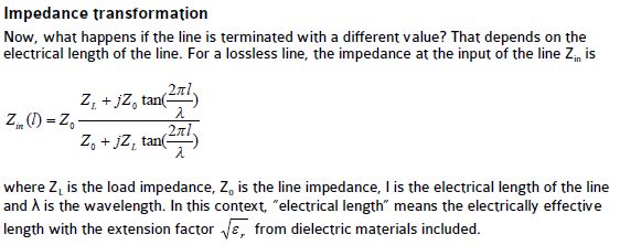
I have a rookie question but i haven't managed to fully understand it so here it goes.. I want to transform a 50Ω source impedance to another impedance R+jX. At the end of the line there is a load impedance R-jX (the output is conjugate matched). this matching network consists of a 50Ω transmission line (at the side of the source) and a 100Ω quarter wave line in series. So the signal starts from the source and sees 50Ω (the first segment) and so reflection occurs. But when it reaches the 100Ω line some power will be reflected back right? So even if the matching network is lossless how can i say that no power is lost in the impedance transformation network as soon as a portion of it will be reflected back? Or should i consider this reflection as a loss similar to conductor loss for example?
I have a rookie question but i haven't managed to fully understand it so here it goes.. I want to transform a 50Ω source impedance to another impedance R+jX. At the end of the line there is a load impedance R-jX (the output is conjugate matched). this matching network consists of a 50Ω transmission line (at the side of the source) and a 100Ω quarter wave line in series. So the signal starts from the source and sees 50Ω (the first segment) and so reflection occurs. But when it reaches the 100Ω line some power will be reflected back right? So even if the matching network is lossless how can i say that no power is lost in the impedance transformation network as soon as a portion of it will be reflected back? Or should i consider this reflection as a loss similar to conductor loss for example?