Continue to Site

Welcome to EDAboard.com

Welcome to our site! EDAboard.com is an international Electronics Discussion Forum focused on EDA software, circuits, schematics, books, theory, papers, asic, pld, 8051, DSP, Network, RF, Analog Design, PCB, Service Manuals... and a whole lot more! To participate you need to register. Registration is free. Click here to register now.

[PIC] Microcontroller ESD level 4 pin protection

Status
Not open for further replies.

rocky79

Member level 5
Joined
Sep 20, 2010
Messages
83
Helped
1
Reputation
2
Reaction score
0
Trophy points
1,286
Activity points
1,903
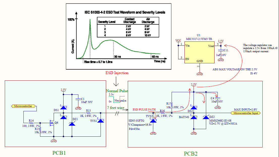
I have been looking for a level 4 ESD pin protection on microcontroller pin( pic16f1503).
The micro digital input pin is used to measure pulses between 50us to 200us.

Do you think a circuit like this would work?

R=500 ohms and
C=0.01uF
VESD=V0=15kv ( Level 4)

Vc=V0(1-e^(-t/RC))
Ic=(V0/R)*e^(-t/RC)

the RC filter will take 1.67uS to charge to 5v however the deadly spikes only last 10’s of nano-seconds.
The initial spike current at t=0 is V0/R=(15kv/500)=30 amps.
In order to conduct this damaging current away from the protected component I added a TVS diode in parallel with the RC.
What do you think about this TVS from littlefuse part# SD05C it has 5v reverse working voltage and clamp at 14.5v 10amps?

Any other suggestions will be appreciated.
ESD-Protection2.jpg

**broken link removed**
 
Last edited:

Hi,

Just to clarify .. the horizontal line is directely connected to the port pin?

If so, i recommend to use a series resistor between ESD source and port pin, so that here the volrage drops and the power is dissipated.

I have good experirnce wit a two stage protection. Directely at the pcb connector use yor tvs with short connection to a ground plane.
At this point most of the power is disspated by the tvs and voltage is limited to aboug 15V. Then use a series resistor to the port pin. This ensures a voltage drop an a current limit. Directely at ghe port pin of the micro use a double schottky diode to GND and VCC (close to a capacitor). I often use BAT54S. Select the resistor value about 100 ohms if possible. This limits the current during the short peak to (15V - 5.5) / 100 ohms = 95mA.
If your series resistor needs to be lower than 10 ohms you may consider schottky diodes with higher current rating.
(The BAT54S will survive a higher current pulse, but voltage drop may limit protection)

Klaus
 
You could also insert a small inductor in series with the signal line outside the first potection, this will act as an increased impedance for the fastgoing ESD pulses.
 

Hi,

You could also insert a small inductor in series with the signal line outside the first potection, this will act as an increased impedance for the fastgoing ESD pulses.

I personally avoid this.
It is true, that the impedance increases, therefore the current decreases.... as long as the core doesn´t saturate.
And keep in mind, that an inductor doesn´t dissipate power, therfore the energy coming from the ESD pulse is not reduced. (for sure a real inductance has losses...)
So if you look at the current with a scope you will see decreased current but increased time.

If you use an inductor, then choose one that is especially designed for ESD protection (WUERTH is one manufacturer i know, www.we-online.de)
Also wuerth has a lot of information and some sample kits for ESD, EMI, EMC...

Klaus
 
Klaus,

Thank you for your feedback. I have implemented your suggestion in the circuit below. Please comment with suggestions or possible improvement.
To give a brief overview. There are 2 circuits one on each PCB seperated by 7 feet wire.
The one on PCB1 sends a communications signal( active low ) to PCB2 over a 7 feet wire.

My goal is to protect the 2.5v signal going to the microcontrooler from ESD spikes.
I have added the following parts:
TVS 450W part# SD05-01FTG
BAT54S shotcky diode
and a 2.7v zener diode as a protection diode for the 2.5v supply part# MMSZ4682
( I didn't want to add a lower zener voltage close to 2.5v just because
current consumptiton should be as low as possible during normal operation.)

All components should consume less than 10uA in standbby mode.

**broken link removed**
 

Attachments

  • Circuit-Feedback3.PNG
    Circuit-Feedback3.PNG
    50.5 KB · Views: 109
Last edited:

Hi,

Some hints..
* C2 is discharged by Q6 without current limit. This may cause problems. Q6 fail and high EMI.
* you need to connect both gnd to transmit the signal
* R13, R16 and C3 build a low pass filter for falling edge, expect a delay of 20us
* R17, C2 and C3 build a low pass filter for rising edge, expect a delay of 200us
* as you said the zeners may be slightely conductive. This is temperature dependent. It keeps VCC low on a high power burst pulse on signal wire. Do you expect that high energy pulse? Most micros can easily survive 3V3 on VCC, so a 3V3 zener may keep problems away.
* use a shielded cable. Even better if you use a shielded cable with differential wires and use differential signalling.
* you may consider using a FOC/LWL instead of copper wire, this avoids all your problems.

Klaus
 
Thank you for your reply.
Do you suggest removing the cap c2 and c3? or lowering the inline resistor to maybe 100 ohms to reduce the delay?
But that will limit protection from ESD current. The TVS clamps to 16.8v
The microcontroller is low power and absolute max input is 2.8v and 4v
Supply to vdd.
So a 2.7 Zener should provides decent protection specially since the Zener test current is at 50 ua.( low current, quick to regulate)

I tried searching for LWL cable, is this fiber optic?
 
Last edited:

Hi,

lowering resitor value: If the delay is ok for your application, then don´t change it.

If you lower it, then current increases. TVS clamps to 16.8V, VCC is 2.5V. Difference is 14.3V. subtracting 0.5V of BAT54 then at resistor is 13.8V. with 100R you get max 138mA. An ESD pulse is short in time. maybe 10us.
This current pulls up VCC with it´s capacitors: Max Vcc voltage is 4V, difference is 4-2.5V=1.5V. with 138mA, 10us, and 1.5V this gives a min. capacitance of about 1uF. So you need at least 1uF of VCC capacitance.
I recommend to use at least 10uF in total of all VCC capacitors.

I´d say its safe to lower it to 100 ohms.
****

Yes, LWL is german, FOC is english = FiberOpticalCable.
For industrial solutions i use HFBR types of AVAGO. It´s easy to use, for prototype you can cut the FOC carefully with a knife, or buy made-up cables.... There may be cheaper solutions.

You may also consider IR: IRDA, or remote control hardware...

Klaus
 
Thanks again klaus, ESD pulses last in several nano seconds peak. I am inclined to remove cap c2 and c3 because the active low pulse that I am sending is 50us wide and that is feeding into the microcontroller interrupt input pin. What do you think?

I would rather keep the resistor then at 1k that keeps current low into VCC.
What do you think about the Zener diode part#MMSZ4682? If you have better suggestions please share it.
Thank you.
 
Last edited:

Hi,

interrupt input is OK. Check if your microcontroller can handle slowly rising signals. If not - you may need a schmitt trigger.

Zener is OK.

Klaus
 
I have made an update to the circuit protection.
I don't think that zener diode is needed since the voltage regulator will clamp voltages at its output tp 2.5v and since it can source current level up to 150mA therefore it can handle incoming current up to 250mA.
A better place is maybe to connect the zener to the microcontroller input. What do you guys think?
 

Attachments

  • ESD-Input-Protection.pdf
    114.6 KB · Views: 132
Last edited:

Hi,

source current level up to 150mA therefore it can handle incoming current up to 250mA.

this statement depends on the used voltage regulator.
Most regulators only can source current, but not sink. But for the ESD pulses a SINK is needed.


But i think the solution is OK, because the energy of an ESD pulse is not that much, so the capacitor may keep voltage in a safe level.
Please be sure you have a low impedance (for high frequency) path from positive schottky diode to capacitor. and then to GND.
To be safe you could place a 100nF X7R capacitor next to the BAT54S, VCC to GND.

Klaus
 
Thank you Klaus. I appreciate your input.
 

Status
Not open for further replies.

Similar threads

Part and Inventory Search

Welcome to EDABoard.com

Sponsor

Back
Top