Continue to Site

Welcome to EDAboard.com

Welcome to our site! EDAboard.com is an international Electronics Discussion Forum focused on EDA software, circuits, schematics, books, theory, papers, asic, pld, 8051, DSP, Network, RF, Analog Design, PCB, Service Manuals... and a whole lot more! To participate you need to register. Registration is free. Click here to register now.

Microcontroller based energy metering for Solar System

Status
Not open for further replies.

asimraufawan

Member level 2
Joined
Jul 7, 2008
Messages
50
Helped
0
Reputation
0
Reaction score
0
Trophy points
1,286
Activity points
1,653
Dear All,

I need to built a circuit to measure energy supplied by solar system . The system is providing 60 Watt load separately to two houses by one inverter 12 DC input & 220 VAC output. The maximum current consumption of one house is 0.27 Ampere at 220 AC. Here i want to built a microcontroller based circuit so that i can measure the energy consumed by two houses in 24 hours of time.

The conditions are as follows.

1. 10 units of quota for each house in one month.
2. 0.3 units will be allocated to one house in 24 hours.
3. There will be two analog signals from C.T
4. If one house consumed 0.3 units before 24 hours cycle the supply will cut off through relay.
5. If the 0.3 units will not consumed in 24 hours the energy calculation will automatically reset for next 24 hours cycle.


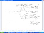
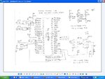
Above conditions are the main requirement other than this do i need the clock IC for 24 hours cycle or i can do this in PIC16F877A, i have build a circuit diagram kindly let me know is it correct or i need to add or delete any component in my circuit.

Also how to select C.T or what will be the C.T rating for this application.

Kindly help me out.

Thanks.
 

Attachments

  • power circuit.JPG
    power circuit.JPG
    65.5 KB · Views: 130
  • control.JPG
    control.JPG
    92.2 KB · Views: 124

Do i need voltage sensing also with current sensing
 

Hi asimraufawan,

Hay why dont you consider Cirrus Logic's CS5460 IC for energy mesuring. The DS1307 interfacing is right.
 

what if i start a counter which count every 1 second till 86400 counts complete the counter will reset the energy measuring as well as if 0.3 units are consumed before 86400 counts (1 day) it will disconnect the AC & after completing the cycle of 84600 it will reset.

If i create this logic do i need to use DS1307. Kindly give a valuable comments.
 

For your clock, go find an RTC (Real-Time Clock) chip. A few vendors make them... check out Maxim, for a start. That will give you a better controlled 24-hour day signal to reference.

For the CT, I'd consider picking up a cheap handheld clamp-meter and gutting it for the parts. Use some know loads to get the AC current vs. voltage curve for the transformer, then develop an equation to map the measured voltage back to a current value in your code. That'd save you trying to spec out a CT.
 

Hi All,

I m still waiting for someone to guide me in detail coz this project is very new to me.

Also i need one more suggestion regarding relay selection what type of relay i should use as i will draw max: 300mA on 220 AC.
 

Your overall flowchart is workable.

The hard part is to make two amp-hour meters, which let you have internal access to an internal overflow pin.

I made a homebrew amp-hour meter. I installed an inline current-sensing wire (consisting of several inches of 12 gauge copper wire). This generates a small voltage across the ends.

I amplify it with an op amp to a range of 0 to 6 volts. Then input it to a voltage-to-frequency converter built around a second op amp.

The pulses go to a 4020 IC ( 14 stage counter). This divides down the pulses. (An alternate chip might be a 4040 or 4060.)

The resulting output pulse increments an LED display showing amp-hours (or milli-amp-hours).

I spent a lot of time experimenting to find:
#1: A suitable frequency range coming from the V-F converter, and
#2: the proper divisor pin on the 4020,
in order to obtain correct readings from the LED display in accord with the amount of amp-hours going through my sensor wire.

My reset signal came from a manual push button. You'll need to reset manually, or use a light sensor to detect sunrise, or else use a realtime clock.

A micro-controller should make the job much easier. The hard job is to obtain a current sense and amplify it to a volt range which can be used by the ADC unit.

As for the relays, there are several ratings to pay attention to.

One is for what voltage and current is needed through the coil. Normally the less of each, the better. If your controller output cannot provide specified V and A, then you'll need to boost it with a pass transistor.

The other rating is volts and amps across the relay contacts. The amount you state can be handled by relays costing under 10 dollars mail order.

Consider getting latching relays. This type doesn't need to be continually energized.With ordinary relays you'll have to provide several volts at tens of milliamps all day long.

Instead a latching relay is pulse-on-pulse-off. Consumes minimal energy. Your controller should have no trouble providing such operation.
 

Hay I have told you, you just consider CS5460a which will mesure your requiered energy consuption a useful example on this link
**broken link removed**
You can go throug this, it shows interfacing of microchip mcu with cs5460, you can replace cs5460 with its improved version cs5460a, your all doubt about how to mesure current and voltage and how to get wattage or energy consuption will be solved in this example
 

I want to add a EEPROM for data backup so that if the 12 volt battery supply is cut off due to battery discharging.
The issue is the EEPROM 24C16 uses the SDI & SCLK pin of PIC controller as well as the RTC DS1307 also uses the same PIN, how will i connect both simultaneously.
 

Hay herewith i am suggesting a schematic with diff MCU you can just get idea of it. It contains CS5460A (for power and energy), RTC DS1307 and EEPROM 24C64.
 

Attachments

  • Wattmeter.PDF
    129.3 KB · Views: 120

Regarding with 24c16 EEPROM i connect pins SDA & SCL with PIC 18F452, what about the rest pins A0, A1 & A2 & WP how will i connect these pins with PIC.

Kindly help me out.
 
Last edited:

This three lines are for addressing purpose so whatever three bits you set (A0,A1,A2), you have to consider this three pins value in your device address while communication over I2C. WRITE PROTECT (WP): The write protect input, when connected to GND, allows normal write operations. When WP is connected high to VCC, all write operations to the memory are inhibited. If the pin is left floating, the WP pin will be internally pulled down to GND if the capacitive coupling to the circuit board VCC plane is <3 pF. If coupling is >3 pF, Atmel recommends connecting the pin to GND. Switching WP to VCC prior to a write operation creates a software write protect function. You can consider datasheet for more detail about device addressing and write protect
 

hi,
am using my custom board whose primary purpose is to read V and I values from cs5460a.
The circuit works fine.
I mean i get full scale and minimum values as well as varying values when i change the V and I from the circuit.
However i have observed that the IRMS from the cs5460 always shows a steady value.
The VRms changes as i change V, but the Irms shows a steady value ie. 0x800000 (24bit) where bit 23rd bit is 2^(-1)
Has anyone one observed such behavior.
The settings done are pretty standard as mentioned in the datasheet.
 

Status
Not open for further replies.

Similar threads

Part and Inventory Search

Welcome to EDABoard.com

Sponsor

Back
Top