Welcome to our site! EDAboard.com is an international Electronics Discussion Forum focused on EDA software, circuits, schematics, books, theory, papers, asic, pld, 8051, DSP, Network, RF, Analog Design, PCB, Service Manuals... and a whole lot more! To participate you need to register. Registration is free. Click here to register now.
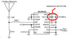
I want to replace the crystal with DS1086 Spread-Spectrum EconOscillator as shown in the last post the reason why i want to do that is to design a multi channel reciever 433.925 - 434.565 MHz with 120khz spacing.
my quation is, is the DS1086 adequate for this substitution (oscillator tolerance)?
The function of the resonator, as far as the RF communications link goes, is to transmit on an expected frequency channel. Somehwere else there is a receiver, that you tune to the same channel, and expect to receive that transmitted energy.
IF you replace the clock resonator with a clock that is jumping around in frequency, then you will be transmitting on random center frequencies. If the span of the transmitted frequencies exceeds the bandwidth of the receiver, then you will be throwing away some of the bits (ie. making bit errors).
So, the question is: with the spread spectrum clock modulating the transmit frequency, are you still within the receiver's bandwidth? If so, you are good to go. If not, you can not use this method.
(BTW, this assumes OOK. It would not work with FSK, for instance!)
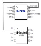
To recieve data on 315MHZ the referance oscillator must be 4.8970MHz. this value is covred by DS1086.
The DS1086 is a programmable through I2C protocol it genarat a frequency signal from 260kHz to 133MHz.
as explened do you think that method can be used?
whats the effecte of tolerance 0.7% (DS1086) on frequency deviation? and how i can design the bandpass filter and match it to antenna input ?
This site uses cookies to help personalise content, tailor your experience and to keep you logged in if you register.
By continuing to use this site, you are consenting to our use of cookies.