Continue to Site

Welcome to EDAboard.com

Welcome to our site! EDAboard.com is an international Electronics Discussion Forum focused on EDA software, circuits, schematics, books, theory, papers, asic, pld, 8051, DSP, Network, RF, Analog Design, PCB, Service Manuals... and a whole lot more! To participate you need to register. Registration is free. Click here to register now.

Measuring & testing maximum current draw from a power supply?

Status
Not open for further replies.

juz_ad

Full Member level 2
Full Member level 2
Joined
Dec 17, 2011
Messages
130
Helped
0
Reputation
0
Reaction score
0
Trophy points
1,296
Visit site
Activity points
2,541
I have a +5V DC fixed voltage power supply that is rated to give (up to?) 1A.

Is there a test circuit that will let me use the current reading on a multimeter to read the maximum amount of current this power supply can actually deliver?

Thanks.
 

I think, you can test the power supply rating with a potentiometer with high power dissipation capability.
You must check two things during testing (while decreasing the resistance value):
-When the power supply lost its rated regulation, because there will be some voltage drops in the transformer and passive devices changing while the output power increasing,
-More importantly you must check the temperature of the elements of the circuit; 80 celcius can be safe point to stop testing considering ambient can go up to 40 celcius and there will be hot spots at the points whwre you can not measure..
 

Typical digital meters have a 10A range but it is very low impedance, and you should not connect it directly to the power supply.

It is better to hook up a load, and to measure the voltage on it.

Dividing 5V by 1A we get 5 ohms, which is the value for testing it within specifications. You should see 5V across the resistor. Its power rating should be 5W or more.

If you want to push it a bit further (briefly), you can try 4 ohms.

Radio Shack sells (or sold) 1 ohm resistors, 10W. I keep several of them for similar low-resistance measurements.
 

It is better to hook up a load, and to measure the voltage on it. Dividing 5V by 1A we get 5 ohms, which is the value for testing it within specifications. You should see 5V across the resistor. Its power rating should be 5W or more.

Thanks Brad,

5(V)/1(I) = 5(R) - I get that, but I'm still not sure how to measure this to show my power supply is delivering it.

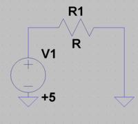
On the image below, measuring the voltage across R gives me 5V regardless of what size R I use (1M, 100K or 1K).

Measuring current in series (Supply > Multimeter > R > GND) never gives me more than approx. 1.4uA. If I replace R with a 1M pot and wiggle it round I get brief spikes up to 300 or 400uA but then it quickly settles back to approx. 1.4uA.

Sorry if I'm misunderstanding this, but what I'd like to set up is something where I can measure or prove a supply of current closer to the 1A that my power supply is rated at.

Thanks.


Simple Ohm's Law tells you that if you have a 5 ohm resistor and the power supply can produce 5V across it then the current is 5V/5 ohms= 1A.
If the power supply can produce 5V across a 4 ohms resistor then Ohm's Law says the current is 5V/4 ohms= 1.25A.
It is that simple.
 

If you want to measure short circuit current, then a short circuit
is what to apply. Practically, I'd use a high wattage 0.1 or 0.01
ohm resistor and measure voltage across it - meter internal
resistance and leads altogether may be too high a resistance
to get you into short circuit current limit territory, and this
resistance is liable to be nonrepeatable across teardown and
even simple bench jostling.

But you may also care about the load-point where you fall
out of spec regulation. Here you need lesser currents and
a finer grained step size to map it out. I've made banks of
switched wirewound resistors for this using 1 and 0.5 ohm
values, series and parallel, letting me get below 0.1 ohms
and step size even smaller. Not linear, not pretty, but a
way to get data on a dollar-limited bench.

Don't care much for E-loads in power supply testing, the
active ones seem to want to fight with the control loop
stability-wise.
 

@jud_az,

A typical trimpot or volume adjustment potentiometer can't handle the power that your supply can deliver; you will just damage your potentiometer.

You should get some rheostats. They are adjustable resistors that can handle power. Rheostats are old-tech, but they're really useful for testing power supplies. For example, see here. Different rheostats (with different sizes and wire thicknesses) are useful for testing power supplies of different voltage and current ratings.

Alternatively, you should consider getting this electronic load.
 

I have a +5V DC fixed voltage power supply that is rated to give (up to?) 1A.

Is there a test circuit that will let me use the current reading on a multimeter to read the maximum amount of current this power supply can actually deliver?
If the current rating is 1A then you should not connect it to a load greater than 1A for good reliability. Long term operation at greater than its rating will likely result in premature failure of the supply even thought it may be able to deliver more than its rating during a test.
 

Overloading a lower supply will probably cause it to overheat which will cook it well done.
Power supplies are not supposed to be cooked.

Some power supplies have current-limiting and have enough cooling that their output can be shorted.
 

Status
Not open for further replies.

Similar threads

Part and Inventory Search

Welcome to EDABoard.com

Sponsor

Back
Top