shaikss
Full Member level 4
Hi Folks,
I need your help in understanding the concept.
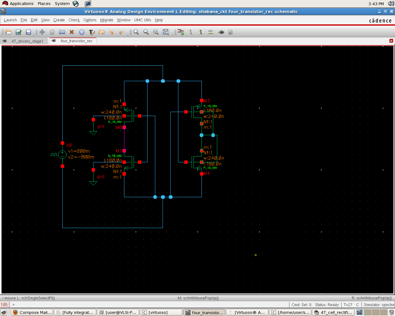
Actually, I am trying to understand the grounding concept here:
Attached is the snapshot:
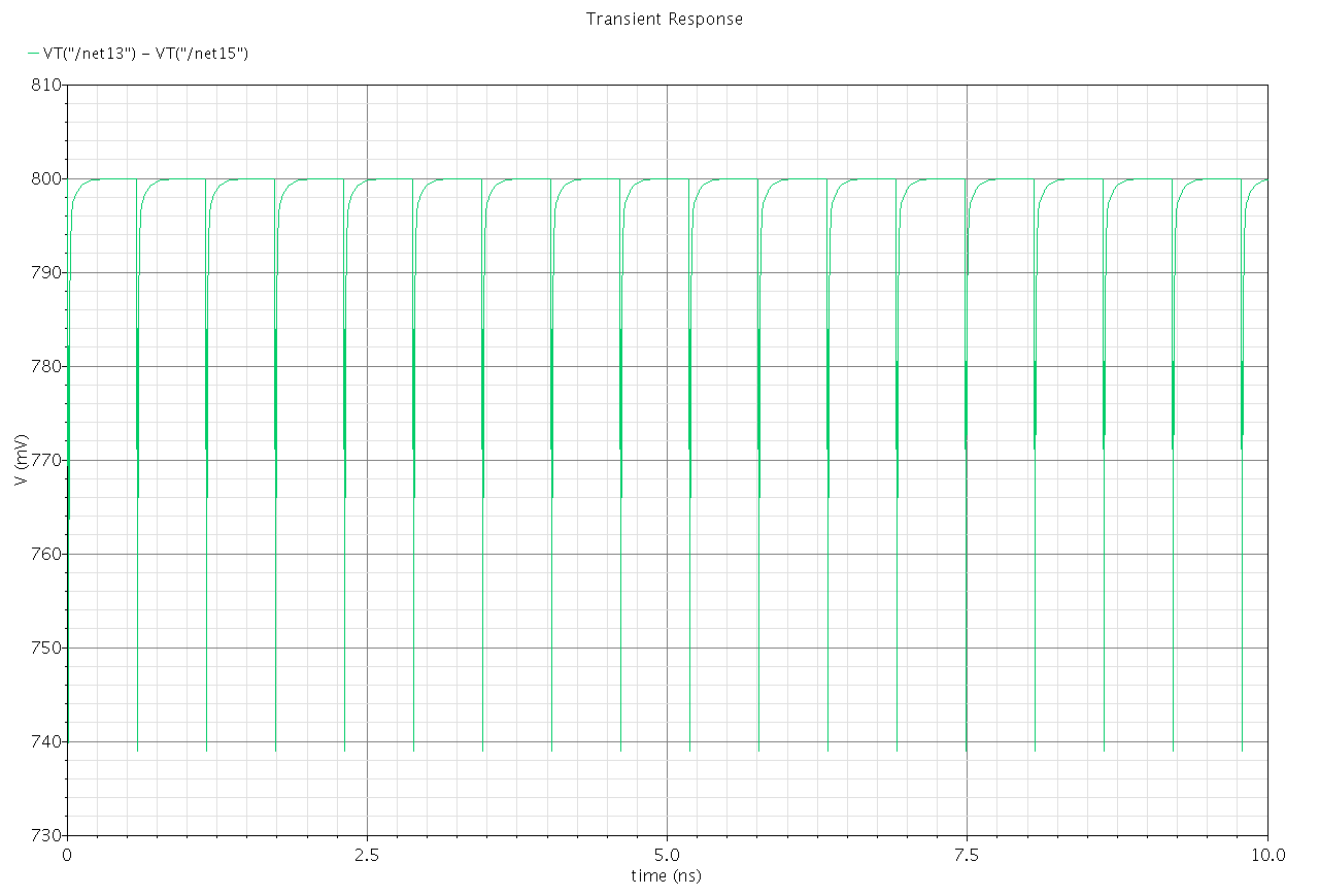
1. Initially, I tried to monitor the voltage between the drain of PMOS(Vh) and drain of NMOS(Vl). Since there is no cap and no resistor, I observed ripple.
Second attachment is the output of the same.
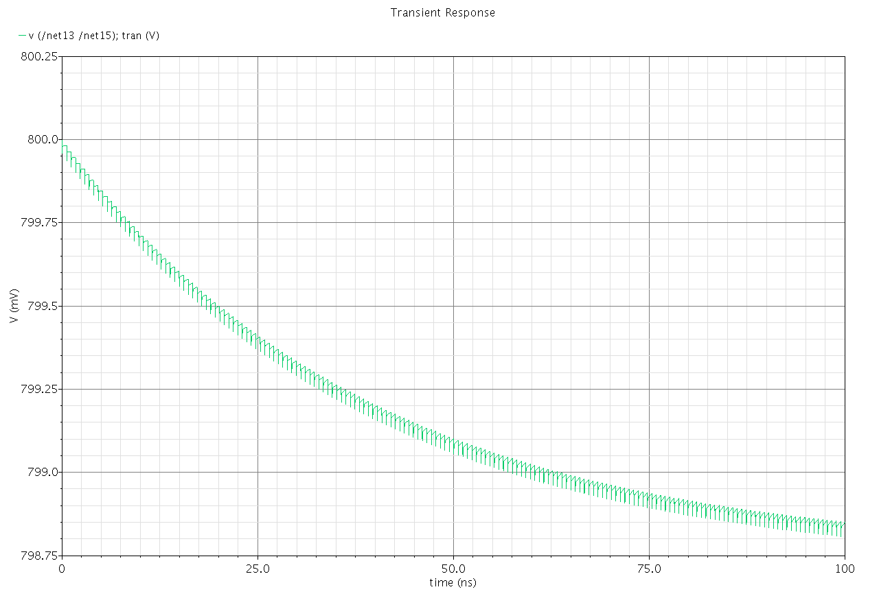
2. Then I connected a cap in between net 'vh' and net 'vl'. Then I observed a drop down in the voltage as shown in third file.
3. Out of my curiosity and to cross-check how grounding impacts: I have conducted below experiment:
I connected one end of cap of 1pf and res of 100K to Vh and the other end of cap and res are grounded. I measured the output between Vh and Vl. As expected, I observed the output as in case 1.
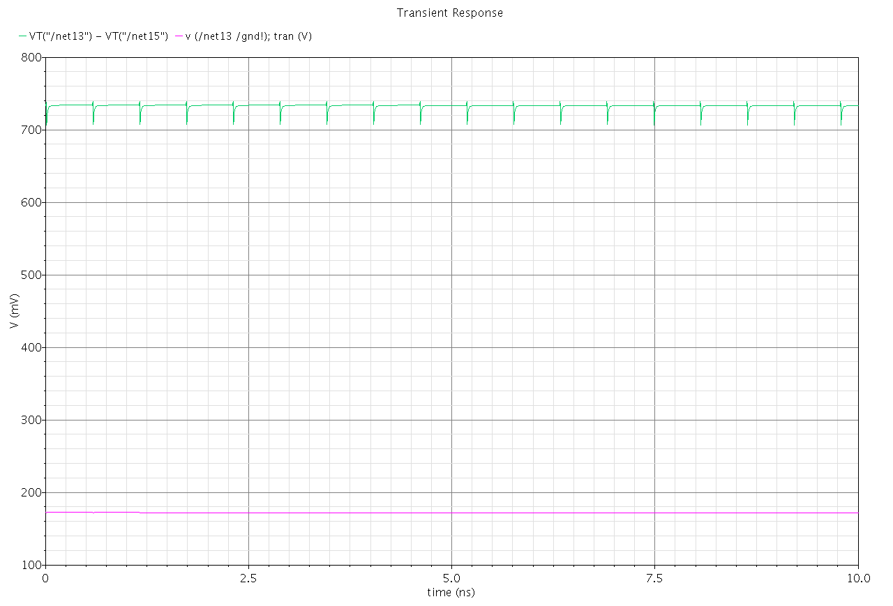
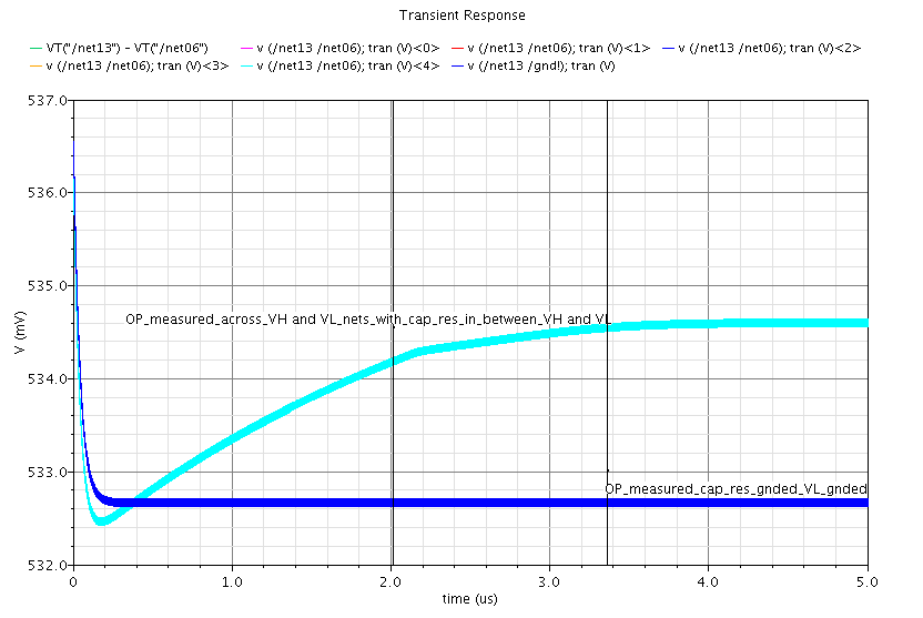
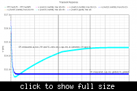
4. I grounded Vl (which shouldn't be case) and grounded one end of cap and res to ground while the other end is being connected to Vh. I observed output across resistor. Fourth file is attached for its output. In this attached file, there are two plots. The plot with lower voltage is the one I have observed when I measured the voltage across resistor when it is grounded and Vl is not grounded.
5. Later on, from my experiment 2, I realized that the voltage is drooping down. So, I increased the time scale and then checked how its actually going on. I observed some interesting results. Fifth file is attached.
Can you explain me why it is happening so?
If I go for N-stage rectifier, the Vl of first stage is always grounded.
So, is it good practice to do so.
Please clarify my queries.

I need your help in understanding the concept.
Actually, I am trying to understand the grounding concept here:
Attached is the snapshot:
1. Initially, I tried to monitor the voltage between the drain of PMOS(Vh) and drain of NMOS(Vl). Since there is no cap and no resistor, I observed ripple.
Second attachment is the output of the same.
2. Then I connected a cap in between net 'vh' and net 'vl'. Then I observed a drop down in the voltage as shown in third file.
3. Out of my curiosity and to cross-check how grounding impacts: I have conducted below experiment:
I connected one end of cap of 1pf and res of 100K to Vh and the other end of cap and res are grounded. I measured the output between Vh and Vl. As expected, I observed the output as in case 1.
4. I grounded Vl (which shouldn't be case) and grounded one end of cap and res to ground while the other end is being connected to Vh. I observed output across resistor. Fourth file is attached for its output. In this attached file, there are two plots. The plot with lower voltage is the one I have observed when I measured the voltage across resistor when it is grounded and Vl is not grounded.
5. Later on, from my experiment 2, I realized that the voltage is drooping down. So, I increased the time scale and then checked how its actually going on. I observed some interesting results. Fifth file is attached.
Can you explain me why it is happening so?
If I go for N-stage rectifier, the Vl of first stage is always grounded.
So, is it good practice to do so.
Please clarify my queries.