eigenroot
Junior Member level 3

- Joined
- Feb 1, 2011
- Messages
- 30
- Helped
- 0
- Reputation
- 0
- Reaction score
- 0
- Trophy points
- 1,286
- Activity points
- 1,557
I have an "intuitive" method of measuring a high dynamic range current decay, but I am not sure whether it is the right way of doing it. The problem is described as follows:
I would like to see a current decay from a photodiode with a high dynamic range. By saying "high dynamic range", I mean it decayed from 100nA down to 100pA or 10pA. Someone suggested use log amplifier. But I didn't have that off my hand, so I tried with a linear preamplifier SR570 that had different transimpedance gains.
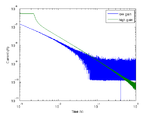
My crude idea was to measure the initial fast and high current with low gain, then the later slow and low current with high gain, and somehow stitch them together to have a full picture. Unavoidably, I would get initial overload plateau with high gain. The example results are shown below:

After getting the transient decay under different gains, I am not sure how to overlay them to get the full current. For example, the input impedances of the amplifier under different gains are different, which may introduce different time delays, as you can see in the figure. There are also other factors. Can anyone comment on what I was doing? Thanks!
I would like to see a current decay from a photodiode with a high dynamic range. By saying "high dynamic range", I mean it decayed from 100nA down to 100pA or 10pA. Someone suggested use log amplifier. But I didn't have that off my hand, so I tried with a linear preamplifier SR570 that had different transimpedance gains.
My crude idea was to measure the initial fast and high current with low gain, then the later slow and low current with high gain, and somehow stitch them together to have a full picture. Unavoidably, I would get initial overload plateau with high gain. The example results are shown below:

After getting the transient decay under different gains, I am not sure how to overlay them to get the full current. For example, the input impedances of the amplifier under different gains are different, which may introduce different time delays, as you can see in the figure. There are also other factors. Can anyone comment on what I was doing? Thanks!
Last edited: