sagi4422
Newbie level 2

- Joined
- Aug 29, 2009
- Messages
- 2
- Helped
- 0
- Reputation
- 0
- Reaction score
- 0
- Trophy points
- 1,281
- Location
- Haifa, Israel, Israel
- Activity points
- 1,317
Hi there,
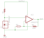
I am building a circuit to measure a sensor I fabricated. The circuit is based on a simple op-amp non-inverting circuit.
The sensor acts like a dynamic resistor, it changes its resistance according to the environment. The problem with the sensor is:
1. That the baseline resistance is very high - tens of MOhm
2. The fabrication method is not stable therefore I have variance between the baseline in each sensor I fabricate
3. The change I am looking to detect are 1-90% change in resistance from the baseline.
Although that, I connected the circuit to an arduino board and the results are reasonable.
I have some questions to advance the circuit:
1. The Vout calculation is Vout=2.5V(1+R2/Rsensor). In case I put a passive resistor in R2, when I change my sensors, I will see different response. I would like to have the ability to control R2 (potentiometer maybe) to receive better sensitivity in such case.
2. I would like to connect it to a MCU (and later to wireless chip). I am not familiar with coding MCUs and found that the simple solution is Picaxe, is it?
The MCU should have the ability to be connected as simple as available to wireless and/or PC.
3. Low power consumption powered by thin batteries.
I know its a lot but only partial help will be helpfull.
Regards.
Sagi