Continue to Site

Welcome to EDAboard.com

Welcome to our site! EDAboard.com is an international Electronics Discussion Forum focused on EDA software, circuits, schematics, books, theory, papers, asic, pld, 8051, DSP, Network, RF, Analog Design, PCB, Service Manuals... and a whole lot more! To participate you need to register. Registration is free. Click here to register now.

MCPCB is no good for mounting different power electronics components?

Status
Not open for further replies.
T

treez

Guest
Do you agree…MCPCB is good for eg LEDs when all things mounted on the MCPCB are the same component…but having say an SMPS power fets and control board mounted on MCPCB would be a mistake…because the chances of all those different components being correctly soldered on MCPCB is very slim.

I worked at an electric drives place, and they had mounted the entire electric drive control circuit and igbts and output caps etc on the same piece of MCPCB, and all the boards needed reworking as many components were not correctly soldered…even when reworking , it was pretty well impossible to get all the different components soldered onto the MCPCB.
Do you agree.. MCPCB is really only for when all the components to be mounted are the same?
 

Using a metal clad PCB requires some thought for the reflow process. The metal cladding might help the PCB maintain a uniform temperature in a vacuum. But the mounting system for the PCB may **** a lot of heat from the PCB, and the thermal gradients created by that are actually worsened by the metal cladding. So you want to keep your PCB thermally isolated from its fixture if possible.
 
  • Like
Reactions: treez

    T

    Points: 2
    Helpful Answer Positive Rating
thanks, so MCPCB has more chance of having components with dry joints then FR4 PCB?
 

If you throw mcpcbs in a reflow process optimized for FR4, then maybe. That's not the PCB's fault though. Without analyzing what causes the faults, there's not much more to say.
 
  • Like
Reactions: treez

    T

    Points: 2
    Helpful Answer Positive Rating
The electric drive place where i worked, they had these MCPCBs...with caps, chips IGBTs,diodes etc etc on them, and many of the components were not soldered properly, and the boards needed endless hand re-working...these boards also had copper bus bars soldered to them..... or shoudl i say they were supposed to be soldered to them......it was very poor.....i am sure there is a problem with soldering lots of different components to a MCPCB.
 

If you throw mcpcbs in a reflow process optimized for FR4, then maybe. That's not the PCB's fault though. Without analyzing what causes the faults, there's not much more to say.

I agree.

First point is to use reflow profiles suggested by metal clad substrate manufacturers.

Secondly there may be necessary adaptions for specific reflow machines. I imagine that different heating methods (e.g. hot air, infrared, vapor phase) are differently suited for metal clad.

I believe it's definitely possible to achieve uniform heating of metal clad PCB during reflow.

Not addressed in this thread, but metal clad PCB can have issues with solder joint durability under thermal cycling. Due to the substrate rigidity, stronger thermal expansion forces are stressing the solder joints, particularly small non-flexible pads of large components.
 
  • Like
Reactions: treez

    T

    Points: 2
    Helpful Answer Positive Rating
  • - Vapor phase should be obsolete with harmful gases to environment
  • - MCPCB is an ideal carrier as heat mass is far greater than components so smooth substrate temperatures can be achieved.
  • -but convection Reflow ovens using Quartz halogen heaters may cause black epoxy chips to over heat from higher absorption, thus if compromised , the substrate does not reach expected reflow temps for smaller parts
  • - this is an ideal match for forced air reflow ovens with far lower temperature gradients , which are needed for low solder defect rates on mixed size attachments with the thermocouple profiles included on the substrate, not just the components as typically done with FR4.


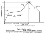
profile.png

So my guess is they used the wrong ovens or wrong profiles for top/bottom in a 5~6 minute cycle with 3'C/s ramp rates.

If the Ovens do not have enough power to overcome the high reflection loss of MCPCB then slower ramp rates are needed down to 1.25'C/s but at the risk of greater aging on LED's but good solder joints. Cree suggests almost a 10 minute cycle with 1.25 ramp up and 1.75'C/s ramp down if using a convection oven.
 
Last edited:

Status
Not open for further replies.

Similar threads

Part and Inventory Search

Welcome to EDABoard.com

Sponsor

Back
Top