Continue to Site

Welcome to EDAboard.com

Welcome to our site! EDAboard.com is an international Electronics Discussion Forum focused on EDA software, circuits, schematics, books, theory, papers, asic, pld, 8051, DSP, Network, RF, Analog Design, PCB, Service Manuals... and a whole lot more! To participate you need to register. Registration is free. Click here to register now.

Maximizing flux through airgap with permanent magnets

Status
Not open for further replies.

Salvador12

Full Member level 4
Joined
Jul 16, 2014
Messages
206
Helped
3
Reputation
6
Reaction score
7
Trophy points
1,298
Activity points
3,950
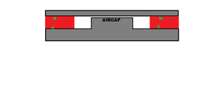
Seemingly a simple question. So I ordered a couple 60x20x5 mm neodymium planar magnets, but I need a homogeneous and strong B field through an airgap.
Previously I had the magnet itself with one side against the airgap, the problem with that is that the field that loops back does so very close to where the magnet ends and disturbs the airgap flux.

I have come up with a simple airgap that uses two metal parts. I hope that with this the field that eventually loops back around the magnet does so away from my airgap so doesn't disturb the airgap field or its direction.
My question I guess is whether routing the same poles which would normally repel through a thick enough metal result in an even flux in the airgap?
I think it should , because metal acts as a smoother for the alike field lines routing them back through the gap and back to the magnets.
Anyway your comments or suggestions?

PS. if I make the gap width and length the same as that of each magnet , how would I roughly know the field strength in the gap if I knew each magnets field ?
I think i can't simply x2 the field because there are losses and metal saturation etc.
 

Attachments

  • MAGNET POLE.png
    MAGNET POLE.png
    18.7 KB · Views: 109

Please add some explanations. Is the white drawing region representing the said "metal"? What are its magnetic properties? Is the device extension perpendicular to drawing plane large compared to vertical size? What is the expected airgap field direction?
 

Please add some explanations. Is the white drawing region representing the said "metal"? What are its magnetic properties? Is the device extension perpendicular to drawing plane large compared to vertical size? What is the expected airgap field direction?
Yes, sorry, so the metal is the grey part, the airgap is the part that is the short open space where the metal is closest together while the magnets are the red cubes on both sides. I mean the whole thing is rather straight forward the field just loops around through the metal.
I hope you see the flux direction even with no arrows based on the pole orientation shown of the magnets.
 

Could a magnetic amplifier be related to what you're doing? Articles connect it with the term 'saturable reactor.' In principle you apply DC current through a winding, making a DC flux field (similar to an electromagnet). Adjust DC power as desired. Reverse direction as desired. This could add or subtract strength from your permanent magnets, as needed.

Articles describe its versatility of functions as it alters AC performance in other windings.


O.k., I see.

Doesn't work with thin polepieces. Need e.g. 10 mm (11 mm in the example) for 0.5 mm air gap to avoid saturation. Still get about 1.8 T flux density in steel.

1671442400447.png


Flux in air gap can be calculated through total reluctance of magnetic circuit. https://en.wikipedia.org/wiki/Magnetic_circuit. To correctly consider saturation effects, FEM modelling, e.g. with free FEMM tool is suggested.
 

Could a magnetic amplifier be related to what you're doing? Articles connect it with the term 'saturable reactor.' In principle you apply DC current through a winding, making a DC flux field (similar to an electromagnet). Adjust DC power as desired. Reverse direction as desired. This could add or subtract strength from your permanent magnets, as needed.

Articles describe its versatility of functions as it alters AC performance in other windings.

No , although it may seem like it but it's not a mag amp, this time it's just an ordinary B field within an airgap.

O.k., I see.

Doesn't work with thin polepieces. Need e.g. 10 mm (11 mm in the example) for 0.5 mm air gap to avoid saturation. Still get about 1.8 T flux density in steel.

View attachment 180280

Flux in air gap can be calculated through total reluctance of magnetic circuit. https://en.wikipedia.org/wiki/Magnetic_circuit. To correctly consider saturation effects, FEM modelling, e.g. with free FEMM tool is suggested.
when you speak of the milimeters needed , did you calculate a rough estimation?
I actually though about 10mm too , since i'm trying to do this cheaply, my friend at his CNC shop has only s355 steel available , it's basic structural steel sheet, I can't find it's permeability online at the moment but I guess a 10mm slice should be thick enough to provide enough flux path even if the steel isn't that "magnetic" aka doesn't have a high permeability like the speciality made permaloy or other stuff.
 

Status
Not open for further replies.

Part and Inventory Search

Welcome to EDABoard.com

Sponsor

Back
Top