JefPatat
Newbie level 5
Hi all,
first post here, I have done several projects before but this time I seem to be really stuck, so her I go.
I have a small circuit that is supposed to communicate with a heating device using some kind of infrared optolink. I attached the schematic.
On my first proto I noticed I forgot to add a capacitor between Vcc and ground, so I soldered one on top of the IC. Because I made a soldering error on the first proto (switched ir led and photo transistor) I made a second one.
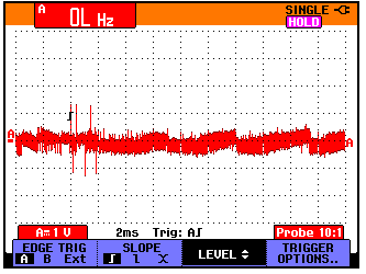
The issue I am observing is that the circuit is just showing some noise around zero on the TX pin.
While making the second proto I only soldered the MAX3232 and its capacitors. I soldered a blob connecting DOUT1 and RIN1 creating a loop back on TTL level. This worked on the PC, I have an USB-RS232 interface and using RealTerm I read back what I was sending. The scope showed levels of +- 7V on TX. I also checked V+ and V- because I saw (in my opinion) strange things on those pins on the first proto. On the second proto I observed the same. V+ a noisy 5V, V- a high frequency signal below zero, somewhere between 0 an -2 if I recall correctly. I was expecting +7 and -7.
First question: what should I measure on V+ an V-?
Since the loopback test was working I removed the blob and completed the print. To test it I put a spoon underneath so the IR LED reflects back to the phototransistor. This seems to work correctly. Both the green and yellow led blink when I send something from the PC. I also measure a nice 5V with pulses to 0V signal on pin 11 T1IN. I however see only some noise around 0V on the TX pin. Not high, not low, zero?
Second question: what am I missing here, this should be a basic circuit |O
If necessary I can provide scope readings or extra measurements.
Thanks in advance,
Jef


first post here, I have done several projects before but this time I seem to be really stuck, so her I go.
I have a small circuit that is supposed to communicate with a heating device using some kind of infrared optolink. I attached the schematic.
On my first proto I noticed I forgot to add a capacitor between Vcc and ground, so I soldered one on top of the IC. Because I made a soldering error on the first proto (switched ir led and photo transistor) I made a second one.
The issue I am observing is that the circuit is just showing some noise around zero on the TX pin.
While making the second proto I only soldered the MAX3232 and its capacitors. I soldered a blob connecting DOUT1 and RIN1 creating a loop back on TTL level. This worked on the PC, I have an USB-RS232 interface and using RealTerm I read back what I was sending. The scope showed levels of +- 7V on TX. I also checked V+ and V- because I saw (in my opinion) strange things on those pins on the first proto. On the second proto I observed the same. V+ a noisy 5V, V- a high frequency signal below zero, somewhere between 0 an -2 if I recall correctly. I was expecting +7 and -7.
First question: what should I measure on V+ an V-?
Since the loopback test was working I removed the blob and completed the print. To test it I put a spoon underneath so the IR LED reflects back to the phototransistor. This seems to work correctly. Both the green and yellow led blink when I send something from the PC. I also measure a nice 5V with pulses to 0V signal on pin 11 T1IN. I however see only some noise around 0V on the TX pin. Not high, not low, zero?
Second question: what am I missing here, this should be a basic circuit |O
If necessary I can provide scope readings or extra measurements.
Thanks in advance,
Jef