Continue to Site

Welcome to EDAboard.com

Welcome to our site! EDAboard.com is an international Electronics Discussion Forum focused on EDA software, circuits, schematics, books, theory, papers, asic, pld, 8051, DSP, Network, RF, Analog Design, PCB, Service Manuals... and a whole lot more! To participate you need to register. Registration is free. Click here to register now.

Making use of resonance in transmission lines

Status
Not open for further replies.

venn_ng

Member level 5
Joined
Mar 26, 2017
Messages
87
Helped
1
Reputation
2
Reaction score
1
Trophy points
18
Activity points
645
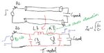
Let's say there is a digital logic driving a capacitor Cload through a transmission line. If we have a really thick metal for the transmission line, such that wL>>R at the frequency of operation and the skin effect is minimal, then does it make sense to use this inductance to boost the rise-time at Cload. We can do this by choosing Rs slightly below the Zo of the Transmission line but not too below to cause ringing. In other words, we make use of reflection to boost the rise time. This can help in reducing power in the driver and pre-driver.

Is there a flaw in the above argument or any possible issue? Let me know if the question is not clear.

The argument follows from the analysis shown in this link

 
Last edited:

Hi, iVenky(https://www.edaboard.com/members/434760/).

Simply consider frequency response of RLC series resonator with capacitor voltage as output.

Here your concerns are not steady state response such as voltage standing wave.

If you can have very basic knowledge about linear circuit theory, answers are self-evident and very easy.
 
Last edited:

If we have a really thick metal for the transmission line, such that wL>>R at the frequency of operation and the skin effect is minimal, then does it make sense to use this inductance to boost the rise-time at Cload.
I don't understand the reference to "thick metal". The quoted link is discussing a lossless TL with variable C load. If "thick" means increased center conductor diameter or microstrip width, it results in reduced ZL, hence the opposite of "wL >>R".

If the question is related somehow to a real circuit design problem, what are fixed and variable parameters? In most cases, CL is fixed (not considering intentional increase), also transmission line length. ZL can be varied within tight limits, e.g. 40 - 80 ohms in a PCB design, Rs can be varied over a wider range.

Following impedance matching rules, you'll choose Rs = ZL and get a perfect first order transition with capacitive load. Risetime is however limited by Rs*Cload time constant. With Rs < ZL, you get overshoot and a certain ringing, rise time is however reduced. If short rise time is your major objective, you may want to accept a certain (10 -20 %) overshoot.

Suggest to use a circuit simulator like LTspice and simulate the discussed setup.

Sorry, if I wasn't clear before. Let me rephrase this question. Let's say the transmission line has some attenuation. In that case, if I just match Rs=Zo, then there would be a rise time degradation. So dropping Rs<Zo makes sense to improve rise time, right? Yes, it's a circuit design problem and I am seeing an optimum point < Zo and not at Zo if I am interested in reducing the rise time without much overshoot.

In general, if it's a digital circuit, we try to place repeaters (like another driver) along the way to reduce the length of transmission line to mitigate the effects of reflection, but I feel it makes more sense to make use of reflection to boost rise time without adding repeaters. This saves power a lot.
 
Last edited:

if I just match Rs=Zo, then there would be a rise time degradation.

You seem to misunderstand transmission line behaviour. The line has distributed LC and behaves as a signal source with R=Zline. If you change the load resistance (purely resistive), the instantaneous voltage at the load will change, but signal shape and rise time (e.g. 10% to 90%) doesn't change.

You might want to use a circuit simulation tool and do some numeric experiments.
 

I have attached a picture. This is what I am trying to state. If there is attenuation in TLine, there is a potential way to reduce power at the source by increasing rise time at the source. However, the load would see sharper rise time due to reflection (or resonance). This value is actually slightly below Zo, Rs<Zo rather than at Zo, as it would just transmit the signal with attenuation at Rs=Zo and degrade the rise time at the load.
 

Attachments

  • Capture.JPG
    Capture.JPG
    88.7 KB · Views: 78

I believe, I already answered your question. Yes, Rs < ZL will result in smaller risetime, but also overshoot and ringing. You can try to find an optimal Rs with only small overshoot and ringing, typically not much smaller than ZL. Risetime reduction is neither large.

I don't see a significant effect on driver power.
 

I don't get why the impact will be small. If, let's say the resistance of the transmission line is higher then boosting using this technique can help a bit in getting better rise time
 

Literally, what's the difference between small and "a little bit"?

1592123488866.png

It would be useful to discuss actual values of TD and CL. In my example, reducing Rs from matched 50 ohms to 45 ohm speeds up the edge, overshoot starts at 40 ohms.
 

Status
Not open for further replies.

Part and Inventory Search

Welcome to EDABoard.com

Sponsor

Back
Top