Welcome to our site! EDAboard.com is an international Electronics Discussion Forum focused on EDA software, circuits, schematics, books, theory, papers, asic, pld, 8051, DSP, Network, RF, Analog Design, PCB, Service Manuals... and a whole lot more! To participate you need to register. Registration is free. Click here to register now.
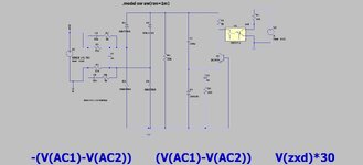
We need a zero cross circuit which gives a falling edge 430us +/-50us before the zero cross. The attached is the best we can come up with. Do you have better?
The advantage of the Type II PD being edge-sensitive (dual D FF) makes it both a phase+frequency detector to have a capture range equal to the entire range of the VCO. This disadvantage is a dead-zone from latency.
Basic law of capacitor behavior: series cap advances sinewave current.
Values in the simulation work for 500 Hz. Voltage across the anti-parallel diodes crosses zero at a point 450 uSec preceding the source. Experimentation will reveal what RC values work at other frequencies.
This site uses cookies to help personalise content, tailor your experience and to keep you logged in if you register.
By continuing to use this site, you are consenting to our use of cookies.