Continue to Site

Welcome to EDAboard.com

Welcome to our site! EDAboard.com is an international Electronics Discussion Forum focused on EDA software, circuits, schematics, books, theory, papers, asic, pld, 8051, DSP, Network, RF, Analog Design, PCB, Service Manuals... and a whole lot more! To participate you need to register. Registration is free. Click here to register now.

3 Phase - Phase Cross Detection (Not Zero Cross)

Status
Not open for further replies.

ngen33r

Newbie level 6
Joined
Jul 9, 2017
Messages
12
Helped
0
Reputation
0
Reaction score
0
Trophy points
1
Activity points
127
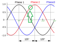
I am looking to detect a point after a phase crossing. I have 3 phases at 24VAC coming from aux windings on a transformer. I have no neutral or earth reference from these taps. I would like to know when phase 2 crosses phase 1 and there is a 3V difference. I bread boarded a comparator with hysteresis, but it does not seem to function properly. Can anyone recommend an improvement or alternate method of detecting this point on a line that has notches, frequency drift & noise (generator supplied power). I could also use a zero cross point with hysteresis if that would be better, but noise from the generator will create false zero points that have to be dealt with somehow.
 

Attachments

  • 3_phase_AC_waveform.svg.png
    3_phase_AC_waveform.svg.png
    45.9 KB · Views: 132
  • 20220811102307736_0001.jpg
    948.8 KB · Views: 144

Hi,

I guess the basic problem is that all your signals are floating to each other.

But to your application:
A 3 V difference between phase 1 and phase 2.
To fully understand the function, I have some questions:
Is it
* "phase1 - phase2", or
* "phase2 - phase1", or
* does not matter, or
* in both directions?

Best if you can draw the expected output signal into your chart.

Is the waveform pure undistorted sine?,Then:
You know: phase1 + phase2 + phase3 = 0, thus: phase1 + phase2 = - phase3, so you theoretically can use one phase only.
24V AC: is it 24V amplitude, or 24V RMS or something else?

What´s the difference between your "comparator with offset" and a "zero cross with hysteresis"?

What is meant by "noise from the generator"? What generator, what noise?

Klaus

I am looking when phase 2 crosses phase 1 and rises 3V above.
The winding is listed as 18VAC RMS 24V peak.
There really is no difference between the 2, but I was instructed to not use a zero cross because the generator (250KVA) is getting smacked with a high current draw every 6 seconds so I have a frequency drift and a dirty sine wave that has notching. I can get a scope trace to better show it.
 

Seems like a natural simple processor state machine problem, ands tell your boss the
UP is a digital comparator.....")

You have 2 events occurring at two different points in time which screams state machine needed,
or at minimum analog memory of the crossover event and value.

Could use ATTINY85 to do this -

1660249528085.png


I think the above is correct, would have to build a proto. Your blocks are converted by tool,
mBlock, into Arduino code and you program the ATTIMY85.

What is max delay from detection to trigger edge you want ?

1660249598380.png


Regards, Dana.
 

To detect the part of the cycle where phase 2 is greater than phase 1....
Seems to me an opto-isolator is made for this task.

Protect it from reverse voltage by installing a silicon diode inline.

Create 3v drop by inserting a zener diode (or the equivalent in plain diodes or led's.)

Mark the moment by creating a spike via capacitor in series (with parallel resistor to perform reset).
 

Another approach, less latency, more accurate -

1660311155814.png


I could have done this with the onchip comparators, used 2 to indicate rising slope, S/H to hold the
crossover value, and a 3'rd comparator to handle the +3V test. That would be even less latency. I just
got lazy. Again same chip, one chip. That approach would be almost a no code needed design.

Whats on chip, multpile copies in many cases :

1660313061177.png


Regards, Dana.
 
Last edited:

Third approach (PSOC, single chip approach again) :

1660594231135.png


Note I did not show all the pins and R dividers to get Vrefs and phases into pins.
Still thinking about DC vs AC coupling into comparators, I think AC makes it
easy to only work with + side of AC waveforms. The basic idea is presented here.
T/H solves analog memory problem needed to then eval 3V point.

1) Use a window comparator to detect when they cross on + side of both
phase 1 and 2.
2) Using a track and hold (T/H) put it into hold when comparator triggers in 1) above.
Use a LUT to hold T/H in hold state
3) Use a third comparator, again window (some hysteresis) to detect 3V point has
occurred.
4) When 3V point drops below value the state machine resets itself to get ready
for next cycle..

The LUT is a simple state machine to control the T/H, when its to track and when its
to hold.

Could also be done as discrete solution. If discrete use single gate logic
for F-F (replace state machine). A quad comparator, and a Vref to get the 3V trip point.


Regards, Dana.
 
Last edited:

Status
Not open for further replies.

Similar threads

Part and Inventory Search

Welcome to EDABoard.com

Sponsor

Back
Top