Continue to Site

Welcome to EDAboard.com

Welcome to our site! EDAboard.com is an international Electronics Discussion Forum focused on EDA software, circuits, schematics, books, theory, papers, asic, pld, 8051, DSP, Network, RF, Analog Design, PCB, Service Manuals... and a whole lot more! To participate you need to register. Registration is free. Click here to register now.

LTSPICE IR2110 Port(Pin) Count Mismatch

Status
Not open for further replies.

metamisers

Junior Member level 2
Joined
May 11, 2022
Messages
21
Helped
0
Reputation
0
Reaction score
0
Trophy points
1
Activity points
215
Hello everyone,

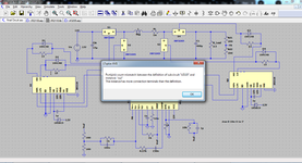
I am trying to simulate this LTspice circuit using a TL494 PWM Generator, IR2110 MOSFET Driver and IRF3205 Mosfet, however I am getting the following error
Final.png

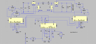
I named the pins for the IR2110 based on the datasheet as shown in the figure below.
IR2110.png

I understand that 4 pins 4, 8 and 14 are NC, and they do not appear in the circuit. I have included everything in the rar files, can someone guide me into how to simulate this circuit properly?
Thank you very much.

Zahid.
 

Attachments

  • Final.png
    Final.png
    120.8 KB · Views: 187
  • Final.rar
    11 KB · Views: 177
  • Final.png
    Final.png
    37.8 KB · Views: 186

Hi,

don't know if this is the problem, but your IR2110_VS connection is wrong. It needs to be connected to the center of the halfbridge.

BTW: this seems not to be the standard IR2110 symbol. Did you design it on your own?

Klaus
 

Well, I took the spice model from the manufacturers website and did the create symbol thing where it automatically creates the symbol. Then I compared the datasheet pin numbers with the ltspice model, in this case, were not the same, and renamed them according to the datasheet. If I am able to run the models without errors, I may be able to correct the VS but the damn model import in LTspice is too bothersome.

Zahid
--- Updated ---

Hi,

don't know if this is the problem, but your IR2110_VS connection is wrong. It needs to be connected to the center of the halfbridge.

BTW: this seems not to be the standard IR2110 symbol. Did you design it on your own?

Klaus
Yes, you are right, the VS should be at the source of the MOSFETs, but first I need ltspice to execute the file and show the waveforms.
 
Last edited:

The error message means what it says. You have more terminals used in the symbol than available in the IR2110 subcircuit file.
--- Updated ---

Do you know that you can assign imported transistor models like IRF3205 to standard MOSFET symbol instead of using ugly block symbols?
 
Last edited:

There are only 11 symbols in the file and I only used 11 of them for the ir2110 driver. I uploaded the wrong picture after adding two more pins, the problem was happening when the .subckt only had 11 pins as written in ir2110.lib file. Yes you are right about the MOSFET, I will import the MOSFET data into the symbol tomorrow morning. On the internet, people wrote to use dummy pins as there are 14 in total but some intermediate pin numbers are missing, for ex. Pin 4 and 8 are NC. They might be the cause of the problem. Still same error after removing dummy pins unfortunately.
 

Don't which SPICE tool uses dummy pins, in LTspice you need a symbol with 11 terminals for a subcircuit with 11 terminals, and - also important - the pin order in the symbol must match the declaration order in the subcircuit, which is not the case for your IR2110 symbol. There are also other problems like static model file definitions in the symbol. 'm not really motivated to clean up everything.

I suggest to get ready made models and symbols from https://groups.io/g/LTspice
 

Status
Not open for further replies.

Similar threads

Part and Inventory Search

Welcome to EDABoard.com

Sponsor

Back
Top