Continue to Site

Welcome to EDAboard.com

Welcome to our site! EDAboard.com is an international Electronics Discussion Forum focused on EDA software, circuits, schematics, books, theory, papers, asic, pld, 8051, DSP, Network, RF, Analog Design, PCB, Service Manuals... and a whole lot more! To participate you need to register. Registration is free. Click here to register now.

Lower down relay coil voltage in rf switch

Status
Not open for further replies.

neazoi

Advanced Member level 6
Joined
Jan 5, 2008
Messages
4,122
Helped
13
Reputation
26
Reaction score
15
Trophy points
1,318
Location
Greece
Activity points
36,951
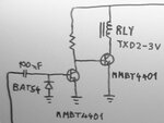
Hello I have this RF switch that is powered by 5V. Any RF at the base of the 1st transistor will deactivate the relay.
The circuit is powered by 5V (battery) but the relay I have available is a 3V one.
How can I use the 3v relay with this circuit?

Some thoughts:

1. place a resistor at the relay switching transistor emitter. (what value?)
2. place a 3V1 zener somewhere (where?), so the relay voltage is reduced when the battery voltage is 5v, but the relay can switch even when the battery voltage drops to 3.1v.

This second point is very convinient in my application, if it can be done.
 

Attachments

  • DSC00179.JPG
    DSC00179.JPG
    23.6 KB · Views: 98

Hi,

lowering 5V down to 3V has already been discussed this week.

You may use:
* a resistor (you need relay current for calcualtion)
* one or more series diodes to generate a voltage drop
* a zener in series to generate a voltage drop
* a voltage regulator do generate 3V
* a lot of others...

Wich one to choose is up to you.

****
Btw. the C with the base and the diode gives a low ohmic and very unliear load to the input. It may harm your RF quality.
At least the first bjt tries to switch ON and OFF with RF frequency. This may cause additional EMI. Depending on RF frequency and bjt speed it may also switch ON and OFF the relay. Not nice.


Klaus
 
  • Like
Reactions: neazoi

    neazoi

    Points: 2
    Helpful Answer Positive Rating
Btw. the C with the base and the diode gives a low ohmic and very unliear load to the input. It may harm your RF quality.
At least the first bjt tries to switch ON and OFF with RF frequency. This may cause additional EMI. Depending on RF frequency and bjt speed it may also switch ON and OFF the relay. Not nice.
Klaus

Thanks!
This circuit at the base, is the only tested one that was able to switch the relay with as low as 100mW.
I have tried voltage doublers or single series diodes with no success at switching at 100mW.

I have not tried to put a shunt capacitor parallel to the diode, I think this would smooth the DC to the base, but it would also delay the time response of the first transistor. Time response is critical because the RF switch will be used to bypass an RF preamplifier and switch the system to TX mode.

RF Power to the base of this transistor is 100mW minimum to 5W maximum at VHF or UHF, so I do not think it is never switched off, neither the relay can cope up with this speed. As said, a small capacitor (maybe 100nF) parallel to the diode may help and ensure base voltage will never be less than 0.6v, but I have not tried it.
 

Leave the base of the first transistor alone. The circuit works by the change in charge of the 100NF. Putting a capacitor in parallel with the diode just attenuates the RF. Try a capacitor from the collector to earth, this will smooth out the RF pulses at the collector. Adjust the collector load so the relay just pulls in the absence of RF.
Frank
 
  • Like
Reactions: neazoi

    neazoi

    Points: 2
    Helpful Answer Positive Rating
Try a capacitor from the collector to earth, this will smooth out the RF pulses at the collector. Adjust the collector load so the relay just pulls in the absence of RF.
Frank

I believe that a cap is not needed even there (I have not tested it though). The relay response is much more slow to cope with the VHF and up positive pulses at the base of the second transistor. But if I find unreliable switching of the relay I will try that, although it will increase the response time a bit (but just a little with a small cap)
I will adjust the collector load accordingly, like you said. I think this will increase the response speed as well.
Thanks for the advices.
 

Status
Not open for further replies.

Similar threads

Part and Inventory Search

Welcome to EDABoard.com

Sponsor

Back
Top