Continue to Site

Welcome to EDAboard.com

Welcome to our site! EDAboard.com is an international Electronics Discussion Forum focused on EDA software, circuits, schematics, books, theory, papers, asic, pld, 8051, DSP, Network, RF, Analog Design, PCB, Service Manuals... and a whole lot more! To participate you need to register. Registration is free. Click here to register now.

Low voltage oscillator (1.5 V to 2.8 V)

Status
Not open for further replies.

nima_1981

Member level 3
Member level 3
Joined
Apr 22, 2010
Messages
61
Helped
0
Reputation
0
Reaction score
0
Trophy points
1,286
Location
Ocean Mind
Visit site
Activity points
1,877
Hi guys
I need to design schematic and i can not use ic
I need low power oscillator that can work with 1.5 V to 2.8 V power supply .
frq need set to 50 Khz and Vpp 1 V square ,
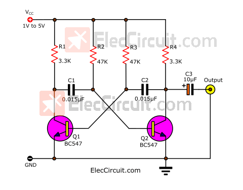
i have this schismatic but i can not bias that transistor work in that range .
Thanks
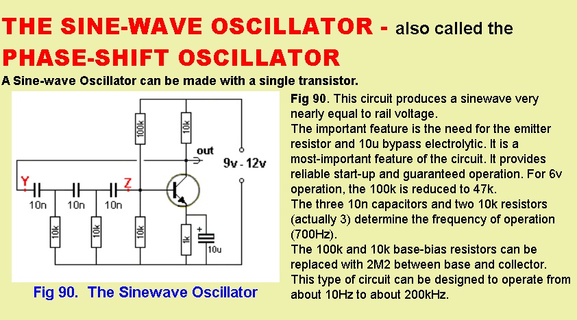
osnew.jpg
 

It is simple to change the bias on the transistor when the supply voltage is reduced. But when the voltage is reduced then the current is also reduced which reduces the voltage gain of the transistor.
The voltage gain must be a little more than 29 times.

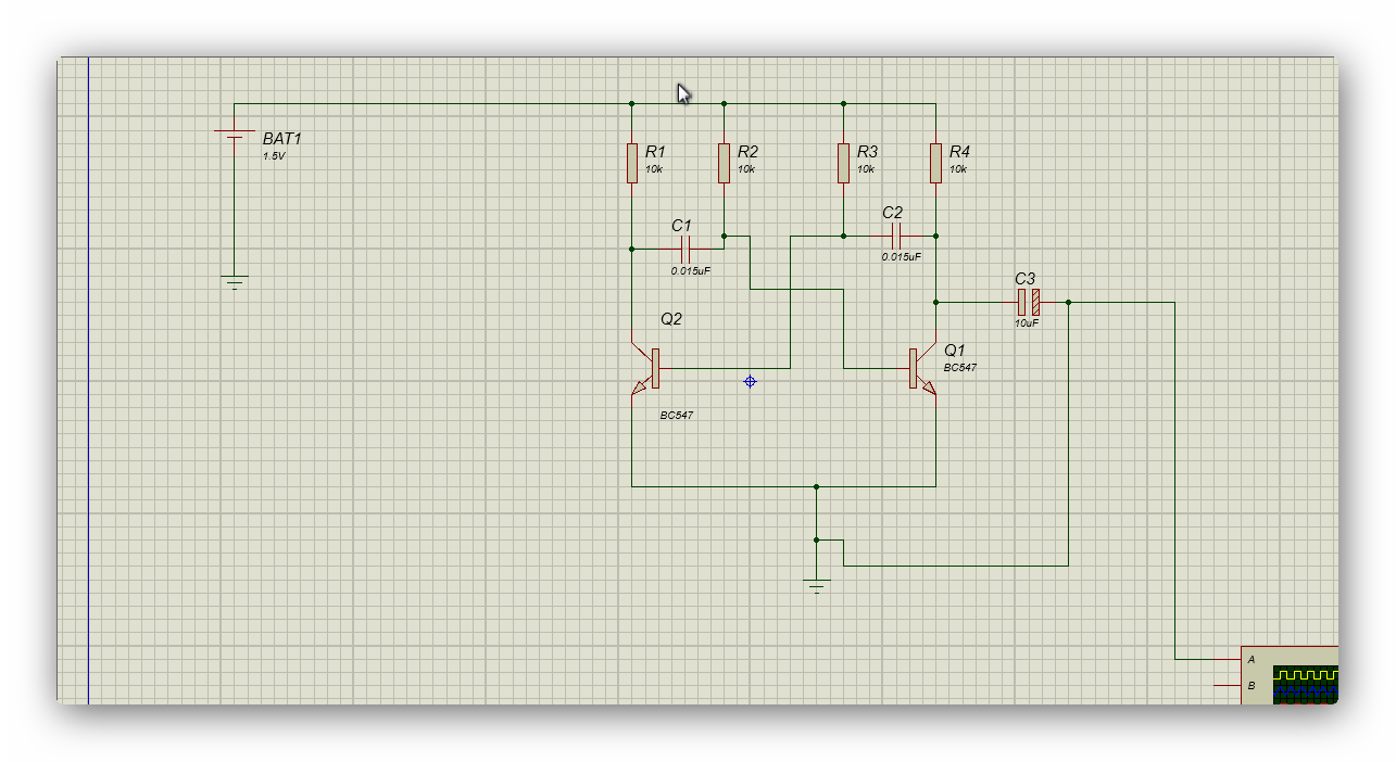
I reduced the supply voltage, reduced the frequency determining resistors, increased the frequency determining capacitors and biased the transistor so that the bias resistors equal a total of 2k like the other frequency determining resistors.
 

Attachments

  • phase shift oscillator.png
    phase shift oscillator.png
    43.9 KB · Views: 246
The phase-shift oscillator gives a sinewave output. The multivibrator gives a squarewave output.
Didn't you want 1Vp-p square(wave)? The output level of the multivibrator is almost the supply voltage when there is no load.
 
The capacitors quickly charged by the collector resistors and slowly discharged by the base resistors. Base resistors must be higher than the collector resistors. If it is not high enough, the output may look like sawtooth wave or the oscillator may not work.

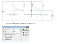
For only simulation, you need initial voltage in one of the capacitors. Set it equal to supply voltage. This will make the circuit unbalance to start oscillation. Practically you do not need any initial voltage in capacitor, the oscillation will start automatically.

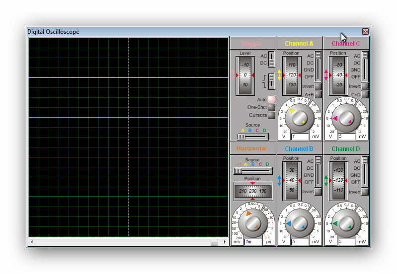
I have Tina-TI simulator. See the simulation pictures below.


Its work fine
thanks to all
but i have a big problem

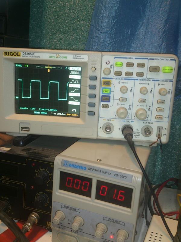
when i increase or decrees input voltage the output change to how i can fix the output on 1 volt ?


DSC_4177_NXPowerLite_.jpg
 
Last edited:

In my post #4 I told you "The output level of the multivibrator is almost the supply voltage when there is no load." Then when the supply voltage changes the output level also changes.
To reduce the output to 1.0V you could make a peak detector circuit drive an automatic gain control circuit. Many sinewave oscillator circuits use them.
 
See the schematic diagram below. Here T4 and P1 forms an adjustable low precision zener. At the beginning apply supply voltage 1.5V and adjust P1 to get 1V output.


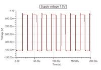
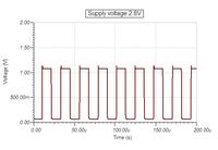
Also see the simulation output pictures below


From the output pictures we see at 1.5V supply the output peak amplitude is 1v, and at 2.8V supply the output peak amplitude is 1.1V.
 
The transistor added to limit the output voltage is also a thermometer. Its limits to a lower voltage when warm and a higher voltage when cool. You might see the voltage drop as it slowly warms up.
 

Why don't you just put a silicon and germanium diode on the output with a (limiting) resistor.
 

T4 and P1 is used to mimic a zener diode, which has breakdown voltage of 1.67 times of Vbe (0.6v) of T4 (so 1.67*0.6 = 1V). As Vbe has temperature dependency (-2.1mv/deg.C) so the total temperature dependency is 1.67*-2.1 = -3.5mv/deg.C. Heat generated by T4 should also be low due to 1V limit. Besides the limit voltage has some current dependency which is reflected in the last picture (1.1V output for 2.8V supply).

Why don't you just put a silicon and germanium diode on the output with a (limiting) resistor.

If silicon+germanium diode was used then temperature and current dependency could not be avoided, also it is easy to adjust to any voltage using a pot.
 
Who said he wants the output accurate to +/- 3.5mV ???????????????????
 

Status
Not open for further replies.

Part and Inventory Search

Welcome to EDABoard.com

Sponsor

Back
Top