Continue to Site

Welcome to EDAboard.com

Welcome to our site! EDAboard.com is an international Electronics Discussion Forum focused on EDA software, circuits, schematics, books, theory, papers, asic, pld, 8051, DSP, Network, RF, Analog Design, PCB, Service Manuals... and a whole lot more! To participate you need to register. Registration is free. Click here to register now.

Low Power Inverter Circuit (12V DC to 230V or 110V AC) Diagram using CD4047 and IRFZ4

Status
Not open for further replies.

rajaram04

Advanced Member level 3
Joined
Jun 17, 2012
Messages
871
Helped
6
Reputation
12
Reaction score
5
Trophy points
1,298
Location
earth
Visit site
Activity points
7,687
Hello again

Here a link with a image is given below :

http://www.circuittrue.com/low-powe...diagram-using-cd4047-and-irfz44-power-mosfet/

Low-Power-Inverter-Circuit-12V-DC-to-230V-or-110V-AC-Diagram-using-CD4047-and-IRFZ44-Power-MOSFE.png

please check if it is all ok or need varaitions

thanksssssss
 

It should work. Do not expect high efficiency and do not expect a sine wave output.

Brian.


okk sir . . .so how much maximum load can be applied at output end here ?

how to calculate theoritically ?
 

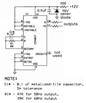
The CV4047 might blow up because the supply voltage will probably have high voltage spikes. I recommend using my attached protection circuit for it.
The transformer shown is a small low power one. The IRFZ44 Mosfets can conduct 31A pretty well if you cool them enough.
The maximum output power to a resistive load will be 31A x 11V= 341W. 1V is voltage loss in the Mosfets.

The output waveform is a crude squarewave that cannot drive many modern products that rely on the higher peak voltage of a sinewave.
 

Attachments

  • CD4047 oscillator.PNG
    CD4047 oscillator.PNG
    43.5 KB · Views: 348

341W is the theoretical maximum INPUT power the transformer, based on a stable condition during each half cycle of primary current and 100% efficiency. The OUTUT power available to the load will be much less because of losses in the transformer and resistive losses in the wiring. The circuit drives the transformer with a square wave which is one of the least efficient waveforms, how much energy is avalable at the output will depend largely on how well the transformer copes under load with square wave drive. If you want a guess, and that is all it is, expect maybe 100W maximum. As Audioguru points out the waveform will not drive many products, particularly inductive ones (motors, other transformers, some lighting, fans...) which do not like sharp edges on their voltage waveforms.

Brian.
 

Status
Not open for further replies.

Part and Inventory Search

Welcome to EDABoard.com

Sponsor

Back
Top