Continue to Site

Welcome to EDAboard.com

Welcome to our site! EDAboard.com is an international Electronics Discussion Forum focused on EDA software, circuits, schematics, books, theory, papers, asic, pld, 8051, DSP, Network, RF, Analog Design, PCB, Service Manuals... and a whole lot more! To participate you need to register. Registration is free. Click here to register now.

Low pass filter design question

Status
Not open for further replies.

bowman1710

Full Member level 3
Full Member level 3
Joined
Nov 8, 2014
Messages
183
Helped
6
Reputation
12
Reaction score
6
Trophy points
18
Visit site
Activity points
1,604
Hi guys,

Im looking at doing a design that will have a cut off frequency of around 2-3Khz with a fast attenuation rate, the components need to be passive and it also needs to block DC. Ive tried a LC filter (4mH with 3.5uF) with a DC blocking cap in series but the attenuation rate it quite slow. Any ideas?
 

Have you considered more stages? Do you know the source and load impedances?

Nuhertz offer a free version of their filter synthesis software (limited filter complexity).
**broken link removed**
 
The load impedance will be 50 ohm, the source impedance will be that of the transformer I guess, maybe I will look at more stages. I was trying to keep component count down, but I guess there is a limit to what you can achieve.
 

Get an estimation of required filter order from intended stop band slope. Simple LC low-pass is second order with 12 dB octave slope. Expect n*6 dB for n-th order.
 

LP.pngLP_TF.png

It sounds like a typical Low Pass "Woofer" filter.Right ??I have rounded the L and C values to nearest practical values.
 
Last edited:
Concept.png

Big boss, the problem i have is that the signal is being coupled onto a line. The design needs to block a HV DC and any signals about 12kHz from both ends. If the signal on the other end is coming in from R9 (so the filter nearest the sinewave receiver) if you have 330nF (C8) you will have 160 ohm to ground. The attached picture is the setup that i am designing to.
 

bowman1710 - it seems that you are looking for a bandpass filter, correct?
Where is your specification (bandwidth and damping requirements)?
 

LvW, I tried one of them but had the same issue with the attenuation. Does anyone have any info on a "nth" order T-shape bandpass LC filter?
 

Does anyone have any info on a "nth" order T-shape bandpass LC filter?

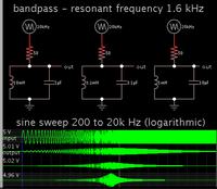
This simulation illustrates the basic idea. You can obtain various rolloff curves by changing the L:C ratio.

Some input resistance is necessary. I used 50 ohms as a ballpark figure.


View attachment 114365

Big boss, the problem i have is that the signal is being coupled onto a line. The design needs to block a HV DC and any signals about 12kHz from both ends. If the signal on the other end is coming in from R9 (so the filter nearest the sinewave receiver) if you have 330nF (C8) you will have 160 ohm to ground. The attached picture is the setup that i am designing to.

I couldn't understand what you intend to do..
Are you trying to block an unwanted signal which has a 12kHz bandwidth to prevent your system from an interference ??
What you need exactly ??
 

Here's an interesting alternative. Series LC, arranged as a bandpass, but with the capacitor split up into two capacitors.

The result is a slower rolloff of the 'bell curve' shape, extending toward the bass region. It's a question whether you can allow bass attenuation.

Notice this arrangement also blocks DC.


Three rolloff curves are illustrated. The shape depends on the ratio of L:C.
 
Brad the rad, that is an interesting arrangement that I didn't consider the only issue i have is that on the HV line I also have high frequency signals of ranging from 25kHz-1Mhz so if you have a cap directly to earth on the output line you have a direct short to ground occur for that signal. At 1Mhz you end up with 39mOhm. The only way round that arrangement is to have the cap in the pF range and end up with a inductor in the 8-16H range which isn't feasible.
 

I also have high frequency signals of ranging from 25kHz-1Mhz so if you have a cap directly to earth on the output line you have a direct short to ground occur for that signal. At 1Mhz you end up with 39mOhm.

After doing some wondering, I think I understand. You are reluctant to short those high frequencies to ground. A capacitor would typically be used to divert them to ground. However at 50 ohms impedance this could be substantial Amperes.

In that case it is preferable to suppress the highs by installing an inductor in series. So you might try adding a symmetrical network, with a second inductor and capacitor in series, to handle signals travelling in the opposite direction.

All L and C values will need to be adjusted, to create your desired rolloff curve, for the overall input and output impedances.

It may require multiple combinations of LC tanks, and LC series networks, to achieve what you are asking.
You may still find you must install RC and RL networks as well.
 
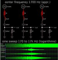
I think i will have to use something similar to this, and accept that the attenuation rate may suffer a little. Big boss i think Brad the rad understands what my issues are. Basically I have a cable with a high frequency signal, this can range from 25Khz to 1Mhz with HV on as well, but i need to pass this 1-3Khz signal though and de-couple it off the cable. Having caps directly on the output to ground will cause an issue. Thanks guys for your feedback and help, much appreciated.


T LC filter.png
 

I think i will have to use something similar to this, and accept that the attenuation rate may suffer a little. Big boss i think Brad the rad understands what my issues are. Basically I have a cable with a high frequency signal, this can range from 25Khz to 1Mhz with HV on as well, but i need to pass this 1-3Khz signal though and de-couple it off the cable. Having caps directly on the output to ground will cause an issue. Thanks guys for your feedback and help, much appreciated.
View attachment 114494
In fact a coupled current transformer will serve you without any trouble.A current transformer that is connected to the main line in series will couple your 1-3kHz signal to the main signal.You can use a filter too after that but you talk about HV and connecting something directly to this main line may be troublesome.This transformer shoule be a ferrite core because iron cored transformers don't work at this frequency.
 

Status
Not open for further replies.

Similar threads

Part and Inventory Search

Welcome to EDABoard.com

Sponsor

Back
Top