Continue to Site

Welcome to EDAboard.com

Welcome to our site! EDAboard.com is an international Electronics Discussion Forum focused on EDA software, circuits, schematics, books, theory, papers, asic, pld, 8051, DSP, Network, RF, Analog Design, PCB, Service Manuals... and a whole lot more! To participate you need to register. Registration is free. Click here to register now.

loop antenna design with specific magnetic field characteristics

Status
Not open for further replies.

jp01

Newbie level 6
Newbie level 6
Joined
Aug 16, 2015
Messages
11
Helped
0
Reputation
0
Reaction score
0
Trophy points
1
Activity points
102
Hello, I come from a mechanical engineering background. I am looking to set up an experiment that requires the use of a custom loop antenna.

I am not using this antenna for transmitting or receiving. I am only interested in the characteristic magnetic field that would be produced when the loop is supplied by AC of a certain frequency.

The diameter of the loop is still undefined at this point. I just need to get an idea of what sort of equipment I would need to produce this magnetic field. I want to be able to adjust the frequency of the AC as much as possible, say between 1kHz-10kHz. Would this be possible? If so, how would I go about setting this up?
 

Your AC source will have a certain amount of power it can provide. Your loop antenna should be compatible with this level of power.

A greater inductance (Henry value) will require less power, and will build a more intense flux field. This goes with larger diameter and larger number of turns.

A plain audio amplifier might do the job. Many are designed to drive an 8 ohm speaker. If you can make your coil impedance 8 ohms then that might be compatible. Ohmic resistance will be a separate parameter, and you must factor that in.

There are online calculators to tell you inductance and impedance for various coil dimensions.
 
The magnetic field of a toroidal coil can be calculated referring to Biot-Savart's law https://en.wikipedia.org/wiki/Biot_savart.

There's a fairly simple expression for the field strength along the axis

H = 1/2 (n I r²)/(a² + r²)^1.5 , r being the coil radius and a the axial distance

Keeping the current constant achieves a frequency independent field strength. Coil voltage will vary according to self inductance.
 

Thank you for the responses guys, I have definitely made some progress with the experimental design work.

My next question is with regards to how to feed the power into the loop. It seems the overwhelming majority of sources I have read talk about feeding the loop using a small 1/5 circumference coupling loop which offers the best efficiency due to the high impedance mismatch. My concern is that the field of the coupling loop will interfere with the field of the main loop. My experiment calls for orienting some sample masses within the field of the main loop.

Are there any other direct feed methods that aren't largely inefficient?
 

My concern is that the field of the coupling loop will interfere with the field of the main loop.

Do you wish to feed the loop continually, or intermittently?

If continually...
Then this project could resemble a metal detector. Two coils oscillate at the same frequency until metal gets close. Inductance is altered in one coil, creating a difference frequency.

If intermittently, then you can disconnect the loop by making a series component go to high impedance. This could be a transistor that admits a sinewave to the loop. By creating high impedance, it is no longer a current-conducting loop, and it has no inductance.

If I understand correctly, the main loop needs to be fed continuously with a AC of a variable frequency. I need to have current being fed into the loop because I'm investigating the radiated field characteristics on a sample mass.

It is worth noting that the sample mass is innately non-conductive and needs to be situated in the center of the loop.
 

It is worth noting that the sample mass is innately non-conductive and needs to be situated in the center of the loop.

Reminds me of store-bought stud detectors, the kind that detect wood behind plasterboard. The explanation I read talked about the instrument detecting dielectric constant. This suggests something to do with capacitance, rather than coils and inductance. I'm not sure whether this conforms to your requirements.

If I understand correctly, the main loop needs to be fed continuously with a AC of a variable frequency. I need to have current being fed into the loop because I'm investigating the radiated field characteristics on a sample mass.

I suppose it depends on the degree of interaction, but I suppose that by feeding energy into the coil continuously, it would interfere with your sensitivity to detect effects from your sample mass.

However, suppose you were to give the coil a jolt every 1/10 or 1/100 or 1/1000 second? Then 'listen' to how it responds and decays? Just a different approach to your plan. I compare it with bats and their sonic radar. They make a loud squeak, then listen for response.
 

Brad,

I suppose I need to be a little more specific with what I'm trying to accomplish here.

I'm investigating possible mass fluctuations of a sample of limestone that will be situated within the center of the loop. This loop needs to be small in order to produce a uniform magnetic field due to constant current around the loop. I chose a small loop antenna due to the geometry of its near field radiation pattern. Some background research indicates that the magnetic field needs to oscillate from positive to negative polarity at a given frequency, hence the need to use a continuous source of AC.

Since I have very little antenna design experience, I'm hoping you guys could enlighten me as to the best approach to conduct this experiment. Is there a better alternative to using a small loop? Is there a better approach that I'm not aware of?

Thanks for your help!
 

I guess you realize your detector needs to be extremely sensitive. However the instigator (electrical energy fed to the coil) must be stronger than the signal you are trying to detect. The instigator will mask your signal, if fed continuously.

To take an example from the bat... Its hearing is shut off when it squeaks. Then it turns on its hearing so it can hear the echo.

----------------------------------------------------------------------------------

Regarding metal detectors, I have used an inexpensive Radio Shack model. I found it was able to detect non-metallic substances. Normally you set its sensitivity while holding it close to the ground. However I tried setting the sensitivity while holding it high in the air. This made it so sensitive that the detector would sound when it got close to concrete, wood, etc.

That is why it is worth considering a metal detecting circuit. Its response is based on slight changes in objects close to its fluctuating magnetic field. That resembles your specified purpose.
 

I don't see how a low frequent magnetic field would interact with limestone or other non-ferromagnetic material.

Brad's report of a metal detector response to concrete or wood can be probably explained by eddy currents in the conductive material.
 

I guess you realize your detector needs to be extremely sensitive. However the instigator (electrical energy fed to the coil) must be stronger than the signal you are trying to detect. The instigator will mask your signal, if fed continuously.

To take an example from the bat... Its hearing is shut off when it squeaks. Then it turns on its hearing so it can hear the echo.

----------------------------------------------------------------------------------

Regarding metal detectors, I have used an inexpensive Radio Shack model. I found it was able to detect non-metallic substances. Normally you set its sensitivity while holding it close to the ground. However I tried setting the sensitivity while holding it high in the air. This made it so sensitive that the detector would sound when it got close to concrete, wood, etc.

That is why it is worth considering a metal detecting circuit. Its response is based on slight changes in objects close to its fluctuating magnetic field. That resembles your specified purpose.

I'm not trying to detect an echo or signal in the sense of of a response emitted by the mass. Basically the mass will be situated on some sort of a scale where it can be monitored for fluctuations.
 

I don't see how a low frequent magnetic field would interact with limestone or other non-ferromagnetic material.

Brad's report of a metal detector response to concrete or wood can be probably explained by eddy currents in the conductive material.

I know it sounds a bit odd, but there is a theory I would like to test which explains how it may be possible to reduce the apparent mass of an object using EM radiation of a certain "flavor".

- - - Updated - - -

I just realized this experiment can be likened to the physics and setup of an MRI machine. I need as much magnetic flux flowing through the center of the coil as possible. Not sure if this helps, but I felt it was worth mentioning.
 

I know it sounds a bit odd, but there is a theory I would like to test which explains how it may be possible to reduce the apparent mass of an object using EM radiation of a certain "flavor".

Perhaps you have heard of a tourist attraction in Florida called Coral Castle? A man named Leedskalnin managed to move large rocks and arrange them with ease. Yet he was neither large nor muscular. How he achieved this feat was not witnessed, nor did he describe it. There are stories that he levitated the rocks by singing to them. He left behind his documents which discuss electrical and magnetic phenomena. Common sense says it should not be accepted as real, yet the stone arrangements are real.

I just realized this experiment can be likened to the physics and setup of an MRI machine. I need as much magnetic flux flowing through the center of the coil as possible. Not sure if this helps, but I felt it was worth mentioning.

If your instruments measure something other than magnetic flux, then it is fine to send as strong a magnetic field as you wish. (Example, if you weigh the rock.) Earlier you talked as though you wish to detect the rock's effect on the magnetic flux.

I understand an MRI sends beams through a body. Sensors at the opposite side detect the strength of the beams coming through the body. A computer algorithm collects data readings from all angles. It compares the readings to deduce the location and density of internal organs. It can only perform this job a slice at a time.

It occurs to me I do not know how a magnetic field can be focussed so finely. One might think the beams are electromagnetic waves, but Xrays are electromagnetic, so I don't think that is done. Anyway I believe rocks block Xrays.

Since I don't know that much about MRI machines, I don't know how to advise about duplicating its operation.
 

Perhaps you have heard of a tourist attraction in Florida called Coral Castle? A man named Leedskalnin managed to move large rocks and arrange them with ease. Yet he was neither large nor muscular. How he achieved this feat was not witnessed, nor did he describe it. There are stories that he levitated the rocks by singing to them. He left behind his documents which discuss electrical and magnetic phenomena. Common sense says it should not be accepted as real, yet the stone arrangements are real.

What if I told you that is exactly what I'm trying to reproduce experimentally? I'm very familiar with Coral Castle and have actually visited the site. Ed's story correlates with some other information I've come across and as a result, has driven me to actually try and recreate his work. I don't want to tarnish this website with some far out theories, I just came hear looking for some good technical advice to help me set this up.

If your instruments measure something other than magnetic flux, then it is fine to send as strong a magnetic field as you wish. (Example, if you weigh the rock.) Earlier you talked as though you wish to detect the rock's effect on the magnetic flux.

I understand an MRI sends beams through a body. Sensors at the opposite side detect the strength of the beams coming through the body. A computer algorithm collects data readings from all angles. It compares the readings to deduce the location and density of internal organs. It can only perform this job a slice at a time.

It occurs to me I do not know how a magnetic field can be focussed so finely. One might think the beams are electromagnetic waves, but Xrays are electromagnetic, so I don't think that is done. Anyway I believe rocks block Xrays.

Since I don't know that much about MRI machines, I don't know how to advise about duplicating its operation.

I would like to utilize some sort of handheld field meter just to get a crude sense of the shape of the field I'm generating. The main focus is to generate as much magnetic flux as possible, and be able to oscillate this field across a broad range of frequencies.

The radiation pattern for a small loop antenna is in the shape of a torus, with nulls perpendicular to the plane of the loop. My worry is that by feeding the loop using a smaller coupling loop, that the coupling loop's field would interfere with the torus shape I'm wanting to use from the main loop.
 

To defeat gravity is science fiction today, nevertheless we've watched science fiction become fact, and electronics has played a big part. It may eventually be possible to defeat gravity with electronic technology, or some other technology.

To send magnetic flux into a rock, you may need frequencies greater than 10 or 100 GHz. This thought came to mind when I recalled that my radio cuts out when I go through a tunnel when listening to AM or FM broadcasts. Therefore stone blocks the 1MHz band. To a lesser extent the 100MHz spectrum.

Further comparison... Microwave oven. It produces electromagnetic energy but you may manage to adjust power settings so it produces magnetic flux only.

Further comparison... Induction stove, produces magnetic flux. There are experimenters who build their own induction coils and post Youtube videos of their experiments.

The above appliances have bulky energy producing components. They draw hundreds of watts of power. I don't know what frequency they produce magnetic radiation at.

Anyway these might give you an idea what sort of equipment you might need to consider.

To see the shape of magnetic flux, you may need to create your own MRI device. I have not heard of film that captures magnetic patterns. Nor a special beam of light we can shine that lights up magnetic flux. Nor a powder we can scatter in the air to tip us off to magnetic flux patterns. Such things are waiting to be invented. There's a mint of money ready to go to their inventor.
 

Thanks again for the insight! I'm moving along fairly quickly now.

My next question is a little more electronics oriented for which I have limited experience.

I've spec'd a signal generator which will produce the test frequencies I will be using. The problem is that the output voltage of these signals will be a few volts. I need to amplify the signal in order to transmit it to the 50 ohm coax which will feed the main copper loop through magnetic coupling at about 10 watts of power.

What would be the easiest and/or most cost effective way to go about this?
 

In simple terms you can apply the waveform to bias a transistor (or mosfet), to boost current through a load (your wire loop). This would need to be designed to handle the range of frequencies.

Or, it should be possible to make an LC oscillator which includes your wire loop. It might carry 10V at 1A, or 20V at 1/2 A, etc. It may be difficult to construct. One topology is a Colpitts oscillator.

If you drive it with a sufficiently high voltage, then your wire loop may start broadcasting electromagnetic waves (in addition to a magnetic field). It is up to you to avoid encroaching on unknown areas of the radio spectrum. The FCC might visit you if you interfere with others transmitting and receiving.
 

Thanks again for the response!

I've read through some material, it seems that the amplified signal will always remain of a single polarity. Is it possible to amplify the signal to oscillate both positive and negative?

I ask this because I would like the loop field polarity to oscillate at the test frequencies.
 

Yes, it is possible to make AC oscillations go back and forth through an LC tank loop. The Colpitts is a simple type.

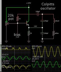
I drew the schematic so the load (LCC tank) is at the right.


The simulation shows (theoretically) 20V at 590mA in the coil, at 54 MHz. To duplicate that much power going through the coil, you can expect to try a lot of experimentation. Same if you want a faster frequency.

> > > Note: The magnetic field may start to resemble an MRI machine. There may be hazard to human tissue if anyone gets close, at this power level, and this frequency. At a high enough power level it could start to emanate photons, which would make it similar to a radio transmitter.

It's up to you to be informed about the risks. Someone who is more expert than I, will be able to tell you more.
 

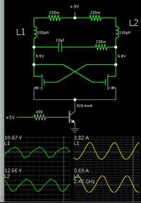
Since you're more concerned with having more Amperes through the coil (rather than more Volts applied to it), here is another oscillator which may work better than the Colpitts.

Greater current through the coil translates into a greater flux field.


I believe you can use a tapped inductor.

Somewhere there needs to be imbalance on startup, so that it begins to oscillate.
 

Status
Not open for further replies.

Similar threads

Part and Inventory Search

Welcome to EDABoard.com

Sponsor

Back
Top