Continue to Site

Welcome to EDAboard.com

Welcome to our site! EDAboard.com is an international Electronics Discussion Forum focused on EDA software, circuits, schematics, books, theory, papers, asic, pld, 8051, DSP, Network, RF, Analog Design, PCB, Service Manuals... and a whole lot more! To participate you need to register. Registration is free. Click here to register now.

looking for two 7pin circular connectors

Status
Not open for further replies.

GammaRadiation

Newbie level 3
Joined
Jul 12, 2016
Messages
3
Helped
0
Reputation
0
Reaction score
0
Trophy points
1
Activity points
23
Hi to all.

Hope that somebody could help me.

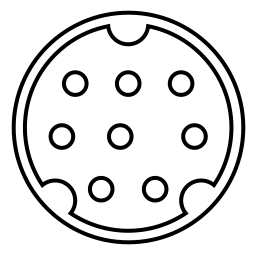
I cannot identify two circular connectors.
AFAIK they should be push-pull type.
I tried to vectorialize one of them in order to find out the size of the pins and the internal layout's geometry, of course I need to buy the females of them.

thanks in advance :thumbsup:

1st
20160707_195409.jpgMacro_connettore_SERIALE.jpgserial_1.jpg

2nd (some 12.5mm external diameter, 9.5mm. internal)
IMG_8852.JPG
 

One of your connectors almost resembles an 8-pin mini-DIN, the serial port on early Macintosh computers. I say 'almost' because the pin spacing is off. It can only be a substitute if you were to do some precise drilling and soldering. Your connector also does not match the 7-pin version.

4862202900_1468340812.png
 
:bang:

thank you Brad... of course I cannot even think about the usage of a connector like that... :roll:

I've seen some Lemo connectors that seem to perfectly match, the fact is that I do not have any experience with those connectors.
 

I have not tried this myself but it ought to be possible to homebrew a custom connector, by pouring hot-melt glue around tubular connectors previously pushed onto the prongs. Solder or crimp wires to the tubes. Then pour hot-melt glue into the cavity. Dust the cavity with flour beforehand.

To make improvised connectors, consider tiny metal tubes scavenged from an extending tv/radio antenna.

It's painstaking. There's a hazard that your assembly will want to stay embedded in the cavity. Or that a tight connector will yank a prong out of the device. However if it succeeds then you have a connector which fits precisely and can be plugged and unplugged.

thank you Bad but... telling the truth I was looking for a definitive, stable solution.
If I cannot find the appropriate connector in the market very probably I will turn on the iron and replace the first one with a common RS232 DB9 connector, desoldering/pulling the original one out and leaving a piece of coaxial cable (some 4 inches) out of the instrument.
 

Status
Not open for further replies.

Part and Inventory Search

Welcome to EDABoard.com

Sponsor

Back
Top