Continue to Site
Follow along with the video below to see how to install our site as a web app on your home screen.
Note: This feature may not be available in some browsers.
CAN WE CONNECT TWS 434 Or Some Module of 433Mhz (without the Holtek Encoder Decoder) To PIC18F4520' TX Pin Directly....
And Can WE Receive It With RWS434 Or Similar Module On Another PIC18F4520
Code Basic4GL - [expand]
Static and noise interference have no effect on it because of the modulation type
CAN WE CONNECT TWS 434 Or Some Module of 433Mhz (without the Holtek Encoder Decoder) To PIC18F4520' TX Pin Directly....
And Can WE Receive It With RWS434 Or Similar Module On Another PIC18F4520
I do it daily and have no garbage problem at all, I'm using my own designed 433.92MHz on board transmitter and a cheap receiver module (not so cheap $24 per module) with PICBASIC programing and I will bet my life on it that you will never receive garbage. I design projects that is used underground in mines and it essential that it is reliable.
ok, so you are not using a genuine cheap TWS434 or TLP433 module after all, which is what Kulkarnitejas (post 23) is asking about. I would be willing to bet my life that you are using some sort of encoding in your code as well, not just sending data out of an IO pin @ 2400 baud.
If a system is to be 100% reliable, not 90%, 95%, or whatever, truly 100% reliability is dependent on some sort of encoding whether it be hardware based or software based.
If you still insist, prove it. Post your code here. Many others have made this claim and have never posted one line of code. (no offense intended, of course)
INCLUDE "Modedefs.Bas"
SerOut PORTA.1,N2400,["A",Code,Zone,Key]
SerIn PORTA.2,N2400,300,Loop2,["A"],Code,Zone,KeyYes, I've done this with these Wenshing parts (I think that these are now made by multiple manufacturers, so YMMV), but as others have said, noise can be an issue. It's been several years, so the details are a bit foggy, but I remember having to send a throw-away byte to 'warm up' the receiver, followed by a unique synchronization byte (ie, 255), and once that was detected by the receiving uC, it was ready to receive the string of data. This just took two or three lines of code in Picbasic Pro. Be prepared for glitches and errors.
If a single value was being transmitted, you could have the transmitter send it three times in a row. So if the byte to transmit was '127' and the receiving uC received '127,5,127', it knew that there was an error and ignored that last transmission.
It was clumsy and crude, but it worked well enough for my non-critical hobbyist application. I ran this at 2400 baud, IIRC. I don't remember if I ever tried anything faster.
Manchester encoding would be better, of course. Or simply adding checksums to your data (like used at the end of every NMEA183 sentence) couldn't hurt.
INCLUDE "Modedefs.Bas"
SerOut PORTA.1,N2400,["A",Code,Zone,Key]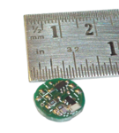
SerIn PORTA.2,N2400,300,Loop2,["A"],Code,Zone,KeyZUZu my transmitter is using 6 components, all SMD's a BFR92A, 2 caps, 2 resistors, saw resonator and a printed loop antenna, I think that is cheap enough, what do you think? for receiver I use a dirt cheap module $7 for reliable work I use a more expensive module $24 USD.I'd evaluate cheapest method against all possible factors involved, not only chipset:
- need MCU for encoding/decoding? If so, why not MCU with transmitter inside? See SilliconLabs, Texas, Adi, Microchip and others
- need one way or two ways. If one way, the cheapest is transmitter + receiver, other ways use transceivers.
- if transceiver, has all RF parts inside eg. LNA, POWER and most important antenna switch & match options?
- need no freq. tuning? use absolute cheep and dirty transmitter: some transistor and saw resonator or use more elevate PLL method, see Micrel which has the smallest part count transmitter in the world (in SOT-23 package)
- one expensive component is quartz crystal involved. Many manufacturers doesn't understand that and made chipsets with absolute idiot frequencies that can be ordered only in 1000+ qty. For this reason, search crystal availability before thinking use that chipset. At least for some can be found that special values on market, for others is absolute impossible to test unless order samples.
- is your product exposed to temp range? If so, you probably need a chipset with AFC or use your own compensation with temp sensor or a TCXO
- finally I'd advice you to read carefully the datasheets and test for final choose. Since is a huge market here, manufacturers often exaggerate their performances. The cheapest is the lower component count (as Micrel or Sillicon Labs) since PCB size is also involved
Cheers,