Continue to Site

Welcome to EDAboard.com

Welcome to our site! EDAboard.com is an international Electronics Discussion Forum focused on EDA software, circuits, schematics, books, theory, papers, asic, pld, 8051, DSP, Network, RF, Analog Design, PCB, Service Manuals... and a whole lot more! To participate you need to register. Registration is free. Click here to register now.

Looking for formula to calculate voltage after resistance.

Status
Not open for further replies.

expertmax

Newbie level 5
Joined
Nov 17, 2011
Messages
8
Helped
0
Reputation
0
Reaction score
0
Trophy points
1,281
Activity points
1,332
Hi everyone !

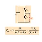
I'm looking for a basic formula to calculate the voltage after the resistor ! My circuit is composed of a resistor (4700ohm), a 12v supply and a 30A motor.

I've hooked the resistor before the motor and I'm looking for the voltage at the motor.

https://i44.tinypic.com/mb0jk4.png

Thank you !!

Max.
 

you cannot have 4700 ohm resistor to a 12v supply with 30ampere motor.
it is not possible to have any voltage after.
 
  • Like
Reactions: IanP

    IanP

    Points: 2
    Helpful Answer Positive Rating
Lets assume for a sec that instead of "30A Motor" you have "30A Load".
At 12V "30A Load" will represent a resistance of roughly 0.4ohm.

Voltage divider calculation should produce a result of roughly 0.00102V ..

:wink:
IanP

See: Voltage Divider
 
Well I'm looking for a straight formula that you can write me down right now using my values because I can't understand what's on the page.

Resistance of the circuit = feed voltage / load amperage, but I don't know how you got your 0.00104 V...

EDIT: Alrighty, I think I got it !

\[final voltage = \left( \frac{supply voltage}{load amperage}\right)\cdot\left( \frac{supply voltage}{resistor value}\right)\]

Which in this case is :

\[\left( \frac{12 V}{30 A}\right)\cdot\left( \frac{12 V}{4700 Ohm}\right) = 0.00104 V\]
 
Last edited:

This is the voltage divider formula: Vx = (Rx/RT)Vs

Vx= the voltage drop at the motor
Rt= Total resistance
Vs= Voltage source

but just like srizbf told you I think that with this resistance your values are not possible.

Imagine that you have the biggest load ! The biggest load would be no motor, just the Source, resistance and the ground.

12V/4700ohms= 0.0026 , so the biggest current you can seek with that circuit is 2.6 mA. And if you put back the motor in the circuit the current will drop again because you add the resistance of the motor at the RT of your circuit.

And if I take your circuit as it is,
series circuit: IT=I1=I2=I3
If you motor seek 30A that means that you would need a 141 kV drop at your 4,7 kOHMS resistance...
V= IR
If you have 30A at your motor you have it thru the resistance, so V= 30Ax4700ohms= 141000V

P(watts)= IV

30Ax141000V= 4.23 MW

Your poor resistance would need to be able to dissipate 4.23 MW without collapsing

mmhh... I don't think you can afford that kind of resistance!

I'm just a beginer electronic student... there may be mistake or misconception in my post, just let me know if you find some!

best regards

Gauthier
 
  • Like
Reactions: IanP

    IanP

    Points: 2
    Helpful Answer Positive Rating
Well I'm looking for a straight formula that you can write me down right now using my values because I can't understand what's on the page.

Resistance of the circuit = feed voltage / load amperage, but I don't know how you got your 0.00104 V...

EDIT: Alrighty, I think I got it !

\[final voltage = \left( \frac{supply voltage}{load amperage}\right)\cdot\left( \frac{supply voltage}{resistor value}\right)\]

Which in this case is :

\[\left( \frac{12 V}{30 A}\right)\cdot\left( \frac{12 V}{4700 Ohm}\right) = 0.00104 V\]

My calculated value is 0.00102V, not 0.00104V ..
The difference is (maybe) not much, but you would fail a test !!!
The formula for simple voltage divider (see attached picture) includes two resistors, top - R1 (in your case it is 4k7) and bottom - R2 (in your case it's the 30A load@12V=>0.4ohm) ..

:wink:
IanP
 

Attachments

  • voltage-divider2.JPG
    voltage-divider2.JPG
    10.4 KB · Views: 77
But IanP, me too it gives me .0010211897 to be exact , but anyway we have both the right voltage divider formula. Mine is good i'm sure, I used it like 50 times in the past month...

We argue on impossible values... but I think it's important to understand why these values are impossible ..

Again like Srizbf said you just can't supply a 30A motor with that circuit, it will not make a rotation in 100 years..

My opinion is, it's not because you plug a 30A motor to that circuit that a 30A current will appear magicaly.

At the best of the best the circuit will give 2.5 mA... 12/4700...

Maybe if he takes off the 4.7kohm resistance it will work, but his 12V power supply will have a rough time ...

Hope that help

Gauthier
 

Maybe we should be asking this question "What are you trying to accomplish with this circuit, and that particular measurement?".

If you have a motor that draws 30A at 12V, then putting a 4700 ohm resistor in series with it will probably not even allow the motor to start turning! Think about the following scenario.

At t=0, when 12V is applied to an idle motor and a 4700 ohm resistor, the motor looks like a simple wire (R=0, short-circuit). That means you will have a 4700 ohm resistor with 12V across it. That will result in a maximum current of (V=I*R), 12V / 4700 ohms = 2.55 mA! If that is a 30A motor, then there isn't a snowball's chance that it'll develop enough of a field to get turning.

If you want to measure a 30A motor's current, you typically use something called a current shunt, which is simply a very low resistance strip of metal with a tight tolerance (like 0.01 ohms, with a 1% tolerance). In this case, if you had a 12V @ 30A motor and a 0.01 ohm current shunt, then 30A through 0.01 ohms = 0.3V drop across the current shunt (so the motor would see 11.7V, instead of it's desired 12V... it should still run fine). Also, the current shunt would be dissipating power (recall Power = V*I = I²R = V²/R). So (30^2)*0.01 = 9 watts. Most shunts will handle that pretty easily. Find some that look like this:
**broken link removed**

or these.

So, what you are trying to do/measure, or was this simply an academic exercise?
 
The problem is not completely defined.
All are trying to resolve it with one assumption or the other.
Original post should add to what exactly is sought.
Also inconsistency in the problem be removed
 

No I was trying to understand which formula to use. I am not in some sort of electronics class or anything, I was using an example and I did not know what values to put in. Anyway thanks for your share.
 

No I was trying to understand which formula to use. I am not in some sort of electronics class or anything, I was using an example and I did not know what values to put in. Anyway thanks for your share.

Ohms Law (V=I*R) will always apply to a resistor. However, motors are a much more dynamic device, so will act differently under varying conditions (looks like a short-circuit initially, but turns into a voltage drop after it gets spinning). Hopefully you learned a few insights from the plethora of responses.
 

It is not that involved it seems!
a 12v supply and a 30A motor

This in steady state would have equivalent resistance of 0.4 ohms. This means 0.4 ohms is connected in series to 4700 ohms.

Pot.jpg


The current trough the circuit is
I = 12/(4700.4) Amps and the voltage drop across the motor would be
V = IR = (0.4 x 12)/(4700.4) = 0.00102 V.
 
Last edited:

Ohms Law (V=I*R) will always apply to a resistor. However, motors are a much more dynamic device, so will act differently under varying conditions (looks like a short-circuit initially, but turns into a voltage drop after it gets spinning). Hopefully you learned a few insights from the plethora of responses.

I learned a lot tonight :p
 

Status
Not open for further replies.

Part and Inventory Search

Welcome to EDABoard.com

Sponsor

Back
Top