Continue to Site

Welcome to EDAboard.com

Welcome to our site! EDAboard.com is an international Electronics Discussion Forum focused on EDA software, circuits, schematics, books, theory, papers, asic, pld, 8051, DSP, Network, RF, Analog Design, PCB, Service Manuals... and a whole lot more! To participate you need to register. Registration is free. Click here to register now.

long time delay retriggable monostable

Status
Not open for further replies.

yassin.kraouch

Advanced Member level 2
Joined
Jul 5, 2009
Messages
631
Helped
40
Reputation
80
Reaction score
40
Trophy points
1,308
Activity points
5,094
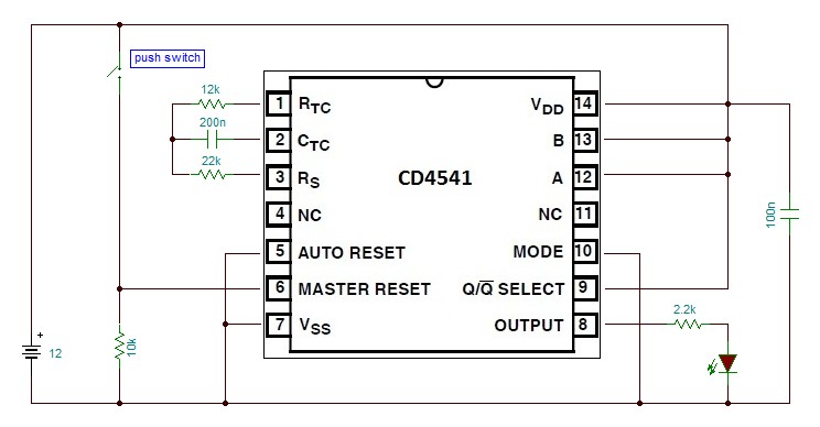
do we have IC that do long time delay, and is retriggable,
the problem with all existing IC that they require a lrge capacitor and big resistor value to achieve long delay,
many thanks
 

You don't give a lot to gone on but the 74HC5555 from NXP produces long delays without large RCs. It has a large counter and does the timing digitally. www.nxp.com
 
  • Like
Reactions: FvM

    FvM

    Points: 2
    Helpful Answer Positive Rating
i was not able to find the datasheet, i found this one, but it looks very old the datsheet **broken link removed**
 

That is the correct data sheet. It is an old part but still in production. Here in the USA, it is in stock at Digikey or elsewhere. It is probably in stock at your local NXP distributor. I suspect NXP sells a lot of these.

Even a utube video! https://www.youtube.com/watch?v=fCh8OSVXC4c
 
Last edited:

CD4541 is retriggerable long duration timer which requires small RC constant. Its MASTER RESET pin is trigger/retrigger input. You need to disable auto reset function when trigger by power on event is not desired.
 

it is clear that this timer can reach 180s output pulse,
 

sorry, it is not clear that this timer can reach 180s, can you please explain ?
thanks,
 

Hi yassin.kraouch
Explain your project/plan where you need retriggerable delay. Then it will be more meaningful to discuss.
 

Hi yassin.kraouch
Explain your project/plan where you need retriggerable delay. Then it will be more meaningful to discuss.
as i expailed before, i want turn on LEDs when the input of the timer goes from low to high,
the LED should be ON for 3 minutes,
 

Hi yassin.kraouch
According to the attached diagram below, you will get near 180s output pulse at the LED when you give a low to high to low pulse at MASTER RESET input. It is retriggerable because MASTER RESET also reset the counter and so counter takes additional time to reach its trigger value.
But after powerup, the circuit automatically gets triggered (without MASTER RESET input signal) and LED stays on for 180s.


thanks ahsan, how abou tthe power consumtion of this circuit,
i want it is a battery powered, so thats why i wan to know thw power consumption,
many thanks
 

For battery operation use CD4541BC do not use CD4541B.
CD4541B's auto reset functionality consumes extra current and also may not work properly at 5v supply. This chip is suitable for high voltage (20v) supply.
CD4541BC is suitable for battery operation. At 25C and at 10v supply voltage, maximum quiescent device current (Idd max) is 10uA.

Here is the link for the datasheet of CD4541BC.
**broken link removed**
 

You can use CD4541B but without auto reset functionality (connect AUTO RESET pin to positive supply). In that case a positive pulse is required at MASTER RESET input after power is turned on.
So what is the source of your trigger signal? ( example: PIR sensor module etc) May be it can provide the trigger pulse after power up.
 

yes a PIR sensor is the source of trigger, so if i understand well, i need just to connect the auto reset to 5V, and after connecting the CD4541B, i connect send a positive pulse to the timer ? is it correct ?
what is the difference coompared to the previous schematic ?
 

When power is first applied to a PIR sensor module, its output goes high, indicating a motion is detected. After some time when adaptation with environment is complete, its output goes low and becomes ready for proper operation. So after power up CD4541B will get a positive pulse at its MASTER RESET input automatically. We dont need AUTO RESET function.

i connect send a positive pulse to the timer ? is it correct ?

PIR sensor will automatically send the pulse.

what is the difference coompared to the previous schematic ?

In the previous schematic auto reset function was enabled. In CD4541B with 5v supply auto reset function is unreliable and also takes extra current.

I guess the the output of the PIR sensor module is 0-3v (TTL level). You need proper interfacing between TTL output of PIR sensor with CMOS input of CD4541B (one npn transistor, one pnp transistor and few resistors can do the job) . Besides you can also use popular CD4060B instead of CD4541B but you may need some extra components (one diode, one pnp transistor and few resistors).
74HCT series can be directly interfaced with TTL, but unfortunately 74HCT4541 does not exist, but 74HCT4060 does exist.
 
Last edited:

Status
Not open for further replies.

Part and Inventory Search

Welcome to EDABoard.com

Sponsor

Back
Top