Continue to Site

Welcome to EDAboard.com

Welcome to our site! EDAboard.com is an international Electronics Discussion Forum focused on EDA software, circuits, schematics, books, theory, papers, asic, pld, 8051, DSP, Network, RF, Analog Design, PCB, Service Manuals... and a whole lot more! To participate you need to register. Registration is free. Click here to register now.

Logic level shift of DC Square wave from Hall Effect Sensor

Status
Not open for further replies.
Joined
Jun 12, 2020
Messages
4
Helped
0
Reputation
0
Reaction score
0
Trophy points
1
Activity points
32
Hi,

I m currently using a Hall Effect Sensor from Allegro (A1212).
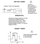
It is attached in the DC motor assembly, and the sensor output goes from 8V to 13.5 square wave pattern for each rotation of the motor shaft.

I need to bring it down to 0-5 V logic level to make my controller understand.

There were some circuits that are given as reference but I m totally confused, on how it works.

As per the reference material I have , the I/p is Raw signal from the Hall Effect Sensor, and O/p is the Conditioned Sensor Output.

Any help regarding this would be much helpful.

Thanks,
Deepan
 

Attachments

  • 1591969180920.png
    1591969180920.png
    94.1 KB · Views: 76
  • 1591969410323.png
    1591969410323.png
    50.9 KB · Views: 64

Hi,

what do you expect us to do?

Verify the circuit? .. without values.

Mind: we don´t have informations about VBatt nor do we have any timing informations.

Klaus

Added:
The allegro A1212 sensor has an open drain output and thus should draw the voltage down to zero volts.
Thus I´m confused how the signal voltage information fits to the A1212 sensor.
 

If for some strange reason the voltages are as you stated, if you drop them through a series 8.2V Zener diode and resistor to ground, the voltage at their junction will be (13.5 - 8.2) = 5.3V and (8 - 8.2) = effectively zero. Is that close enough?

Brian.
 
Hi,

I m currently using a Hall Effect Sensor from Allegro (A1212).
It is attached in the DC motor assembly, and the sensor output goes from 8V to 13.5 square wave pattern for each rotation of the motor shaft.

I need to bring it down to 0-5 V logic level to make my controller understand.

There were some circuits that are given as reference but I m totally confused, on how it works.

As per the reference material I have , the I/p is Raw signal from the Hall Effect Sensor, and O/p is the Conditioned Sensor Output.

Any help regarding this would be much helpful.

Thanks,
Deepan
Hi,
Below circuit may work. I used ISO1211 for a similar purpose.
 

Attachments

  • try.PNG
    try.PNG
    12.7 KB · Views: 74
  • try1.PNG
    try1.PNG
    8 KB · Views: 62
Hi,

what do you expect us to do?

Verify the circuit? .. without values.

Mind: we don´t have informations about VBatt nor do we have any timing informations.

Klaus

Added:
The allegro A1212 sensor has an open drain output and thus should draw the voltage down to zero volts.
Thus I´m confused how the signal voltage information fits to the A1212 sensor.


Neither do I have the values for the circuit, it has been given just for the name sake..... I persume that it has nothing to do with the requirement I have,

If i try to put it straight, I have a device , connected at the motor shaft which gives me pulse for every RPM, for which pulse peak is at 13.2VDc, and pulse lowside voltage is 8.0VDc, and they are equally split for the 180 of rotation of the shaft,

Hence now , I have a pulsating DC signal , that floats between 8.0 to 13.2 VDc, I need to get it to 0-5V range in the same frequency at which it is happening as that of the source, so that my MCU can understand

Hope I have explained a bit clear from my very first post in EDABOARD..
 

If for some strange reason the voltages are as you stated, if you drop them through a series 8.2V Zener diode and resistor to ground, the voltage at their junction will be (13.5 - 8.2) = 5.3V and (8 - 8.2) = effectively zero. Is that close enough?

Brian.
Looks promising... Let me try it out..
 

Hi,
Below circuit may work. I used ISO1211 for a similar purpose.
Looks like one such solution , I was expecting, but I m worrying about the BOM parts, and cost of it.
 

Hi,

still no timing no frequency....when you design such a circuit you need to have at least a raw estimation of the requirements...

My usual way is to use a comparator....


Klaus
 
  • Like
Reactions: ats2

    A

    Points: 2
    Helpful Answer Positive Rating
Status
Not open for further replies.

Similar threads

Part and Inventory Search

Welcome to EDABoard.com

Sponsor

Back
Top