Deepukutty1994
Newbie
Hi,
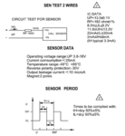
I m currently using a Hall Effect Sensor from Allegro (A1212).
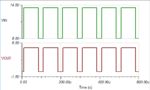
It is attached in the DC motor assembly, and the sensor output goes from 8V to 13.5 square wave pattern for each rotation of the motor shaft.
I need to bring it down to 0-5 V logic level to make my controller understand.
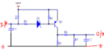
There were some circuits that are given as reference but I m totally confused, on how it works.
As per the reference material I have , the I/p is Raw signal from the Hall Effect Sensor, and O/p is the Conditioned Sensor Output.
Any help regarding this would be much helpful.
Thanks,
Deepan
I m currently using a Hall Effect Sensor from Allegro (A1212).
It is attached in the DC motor assembly, and the sensor output goes from 8V to 13.5 square wave pattern for each rotation of the motor shaft.
I need to bring it down to 0-5 V logic level to make my controller understand.
There were some circuits that are given as reference but I m totally confused, on how it works.
As per the reference material I have , the I/p is Raw signal from the Hall Effect Sensor, and O/p is the Conditioned Sensor Output.
Any help regarding this would be much helpful.
Thanks,
Deepan