Farad22
Junior Member level 2
Hi all.
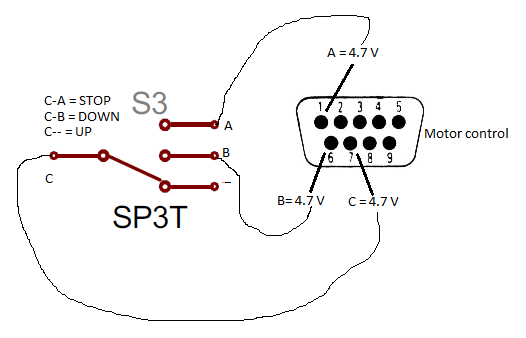
At the moment I'm working on a simple LED indicator (up/down) for a motor controller. It has to indicate if the motor is going in one direction or the other. On the controller there is a control port (D-SUB9) and a switch is connected through a three wire cable to this control port to connect one common wire C to either wire A (up) or B (down). Unfortunately i don't have any more data about the controller.
I suspected that the common wire would be a logic high signal that gets connected through the switch to either INPUT A (wire A) or B (Wire B). I disconnected the cable and switch and measured directly at the control (D-SUB9) connector on the motor controller. The pin connected to wire C measured high (4.7 V). However the other pins connected to wire A and B also measured high (4.7 V). How is this possible when there should be in- and outputs on this control port? I was suspecting the input pins to measure low. My idea was to detect when input A or B is high and then indicate this with two LEDs. If all the voltage are logic high then this isn't possible.
Maybe I overlooked something. Any help is appreciated.