Continue to Site

Welcome to EDAboard.com

Welcome to our site! EDAboard.com is an international Electronics Discussion Forum focused on EDA software, circuits, schematics, books, theory, papers, asic, pld, 8051, DSP, Network, RF, Analog Design, PCB, Service Manuals... and a whole lot more! To participate you need to register. Registration is free. Click here to register now.

Log/Semi-log amplifier outputs

Status
Not open for further replies.

Tamasco

Full Member level 3
Full Member level 3
Joined
Jun 27, 2006
Messages
155
Helped
10
Reputation
20
Reaction score
6
Trophy points
1,298
Visit site
Activity points
2,083
Referring to the attached image file, I am trying to figure out what the output of the second diagram will be. It looks apparent that the reverse (feedback) resistance will be substantially lower in the second case giving a much lower output voltage.

Please, what is the mathematical relation of the input/output voltages?

Many thanks in advance.
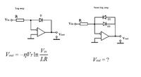


Thank you very much. But will the mathematical relations be the same? I mean the expression for Vout.
 

This circuit displays the log function when you apply a narrow input amplitude, between 0.3 and 0.6 V.
Or, between -0.3 and -0.6V (for the circuit which has 2 diodes).

Since I was not sure about the output waveform, I used a simulator to check. This circuit is a clipping circuit, which limits the output voltage to 0.6V amplitude.
 

Status
Not open for further replies.

Part and Inventory Search

Welcome to EDABoard.com

Sponsor

Back
Top