CQCQ
Member level 3
Hi!I got a simple but awkward problem.
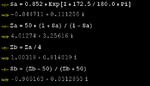
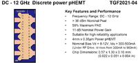
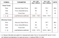
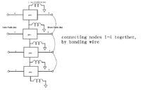
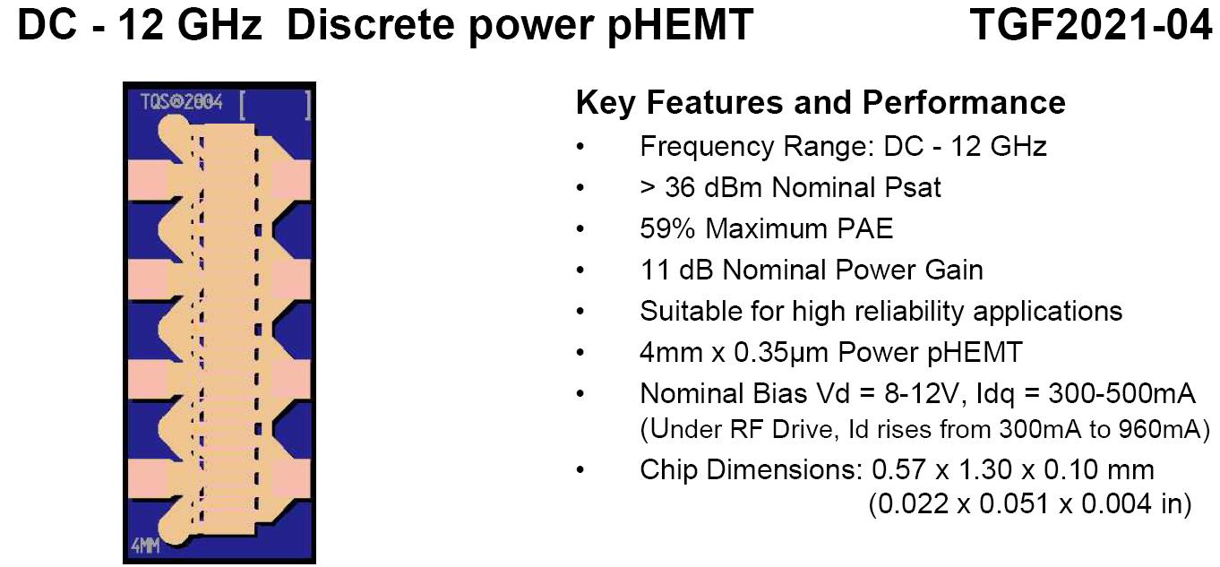
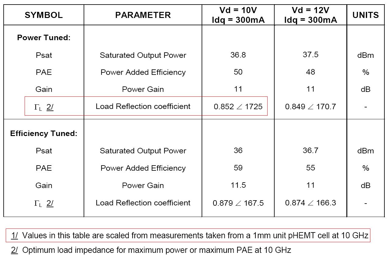
TGF2021-04 datasheet says the load reflection coefficient per 1mm unit pHEMT cell at 10 GHz is 0.852 ∠ 172.5≈4+j2,TGF2021-04 is a 4mm device(four cell ),So,What is the best load impedence when I connect the four cell together?
(4+j2)*4 or (4+j2)/4?
Mega Thanks
-cqcq
:-D:-D:-D
TGF2021-04 datasheet says the load reflection coefficient per 1mm unit pHEMT cell at 10 GHz is 0.852 ∠ 172.5≈4+j2,TGF2021-04 is a 4mm device(four cell ),So,What is the best load impedence when I connect the four cell together?
(4+j2)*4 or (4+j2)/4?

Mega Thanks
-cqcq
:-D:-D:-D