Continue to Site

Welcome to EDAboard.com

Welcome to our site! EDAboard.com is an international Electronics Discussion Forum focused on EDA software, circuits, schematics, books, theory, papers, asic, pld, 8051, DSP, Network, RF, Analog Design, PCB, Service Manuals... and a whole lot more! To participate you need to register. Registration is free. Click here to register now.

Load Current Limitation in LTC7000 High Side MOSFET Driver.

H2M

Member level 1
Joined
Aug 11, 2016
Messages
36
Helped
0
Reputation
0
Reaction score
0
Trophy points
1,286
Activity points
1,624
Hi
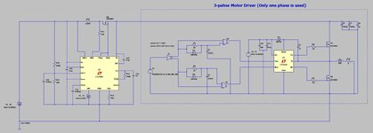
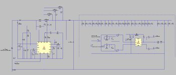
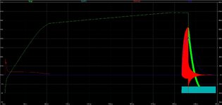
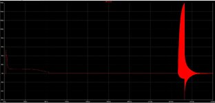
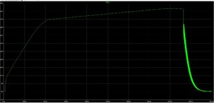
I'm trying to design a 3-phase motor driver. I want to have over current protection in my design, so I have used LTC7000 in order to have over current protection in my bus line. the problem is I can't raise the MOSFET current (Load Current) above 10 Amps! with any shunt resister LTC7000 will turn off the MOSFET when current reach above 10 Amps. Can anybody help me? I attached below my LTspice simulation.
 

Attachments

  • Capture.JPG
    Capture.JPG
    107.1 KB · Views: 253
Hi everyone, I've finally got desire results. I attached my final schematic and simulation curve.

During simulation I had these problems:
1- because of huge capacitance in the output I have a big inrush current (picture 3), so the LTC7000 detect this enormous current and after that disable switches. In order to solve this problem I used an RC filter in the inputs of switches gates to turn on switches more slowly.

2- When we have a big capacitance in the output it takes about 230 ms for LTC7000 to raise switches gates voltage to 62 V (picture 4), before this time we should not start switching in 3-phase inverter. becuase if we start switching, the LTC7000 would never turn on the switches with proper Gate-Source voltage.

3- I also add a RC filter in the path of my shunt resistor to avoid Over Current Detection due to the switching noise.


4 - I add a schottky diode cross my 3-phase inverter because I have an inductive load in the output. When LTC7000 detect an OCP and turns the switches off, this diode will recirculate the current.

5- I add an latch mechanism using R1 and C3 in Timer pin. Because I want to have switches disconnected until the user reset the LTC7000.
 

Attachments

  • 1.JPG
    1.JPG
    132.4 KB · Views: 77
  • 2.JPG
    2.JPG
    145.6 KB · Views: 70
  • 3.JPG
    3.JPG
    134.1 KB · Views: 75
  • 4.JPG
    4.JPG
    151.3 KB · Views: 75
Too bad I didn't see this thread earlier. I've used the LTC7000 in a few designs, with trip thresholds up to 100A.
1- because of huge capacitance in the output I have a big inrush current (picture 3), so the LTC7000 detect this enormous current and after that disable switches. In order to solve this problem I used an RC filter in the inputs of switches gates to turn on switches more slowly.
Yes, you have to implement some sort of RC on the gate to limit the output slew rate, thus providing inrush limiting to capacitive loads. I suggest you will need far more aggressive filtering than what your schematic shows...
2- When we have a big capacitance in the output it takes about 230 ms for LTC7000 to raise switches gates voltage to 62 V (picture 4), before this time we should not start switching in 3-phase inverter. becuase if we start switching, the LTC7000 would never turn on the switches with proper Gate-Source voltage.
To be clear, the rise time of the output should just be dependent on the soft-start capacitance you add to the gate, and the input supply voltage (VBAT in your case). Nothing to do directly with output capacitance (though if Cout is very high, and the soft start is too fast, an OCP can be detected during the soft start).
3- I also add a RC filter in the path of my shunt resistor to avoid Over Current Detection due to the switching noise.
Yes, I've found it very important to mitigate the ESL of the current shunt, especially when the shunt resistance is <5mohm. In one case I actually have a two-stage RC filter to further filter out ripple.
4 - I add a schottky diode cross my 3-phase inverter because I have an inductive load in the output. When LTC7000 detect an OCP and turns the switches off, this diode will recirculate the current.
Not clear what you mean here.
5- I add an latch mechanism using R1 and C3 in Timer pin. Because I want to have switches disconnected until the user reset the LTC7000.
I think you're misunderstanding how the Timer pin works. In my application I use "Fast Turn-Off Mode" by connecting Timer pin directly to Vcc. This mean the LTC7000 responds with minimal delay, and will not automatically retry after an OCP event. If you connect Timer to GND with a capacitor, then this will cause the LTC7000 to basically respond slower, and also it will automatically retry after an OCP (so long as INP is held high). It sounds like you want Fast Turn-Off Mode, but your schematic isn't set up that way. Also I don't think there's any reason to connect that resistor to the Timer pin.
--- Updated ---

Some more general comments:
In your simulated waveforms, there's definitely something not working properly. VBUS and Vgate should rise linearly, for the most part, but in you sim the slope changes drastically two times. I would check that your bootstrap capacitor voltage is not drooping significantly during turn-on. You should increase the TGup resistance a lot, probably at least 10K.

Also be careful when using multiple pass FETs in parallel. They likely won't share current during inrush due to differences in threshold voltage. In practice the temperature coefficient of Vth may cause them to balance somewhat, but this will depend on the specific FET and the inrush current.

As KlausST mentioned before, having a super-fast circuit breaker like the LTC7000 becomes somewhat irrelevant when the output side has such a large bus capacitance. As your simulations show, even after the OCP is detected and VBAT is disconnected, the capacitors can supply a huge surge of current to the load. In my applications I have ~90% of the overall bus capacitance on the input side of the LTC7000. Usually the capacitance on the output side would just be MLCCs or film caps for handling the high frequency ripple, while the bulk electrolytic caps are on the input side.
 
Last edited:
If you do compare bypass capacitor energy content (about 15 Ws at 50 V) with MOSFET SOA, you'll see that it's not feasible to make the MOSFETs dissipate the power loss during capacitor charge.
 
Makes no sense to charge the bus capacitors through a switch. Better use a precharge resistor or analog current source.
When properly configured, the LTC7000 should raise Vout with a controlled slew rate, and thus acts roughly like a current source into a capacitive load.
--- Updated ---

If you do compare bypass capacitor energy content (about 15 Ws at 50 V) with MOSFET SOA, you'll see that it's not feasible to make the MOSFETs dissipate the power loss during capacitor charge.
Agreed, for such a large capacitor bank those FETs will likely not survive. Another good reason to reduce the VBUS capacitance.
 
Last edited:

LaTeX Commands Quick-Menu:

Part and Inventory Search

Welcome to EDABoard.com

Sponsor

Back
Top