Continue to Site

Welcome to EDAboard.com

Welcome to our site! EDAboard.com is an international Electronics Discussion Forum focused on EDA software, circuits, schematics, books, theory, papers, asic, pld, 8051, DSP, Network, RF, Analog Design, PCB, Service Manuals... and a whole lot more! To participate you need to register. Registration is free. Click here to register now.

LM317 current limit circuit blew up

Status
Not open for further replies.
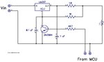
I'd suggest a pragmatic approach. Remove C5 and check if the circuit is behaving according to your needs.
If you look at LM317 load transient response your 2 ms rate is the
dominant system characteristic. The 317 is more than capable of
handling that.

View attachment 163156


Regards, Dana.

Hi Dana,

This is very good news to me :) I was trying to understand this. I think your 2mS comes from 1000mS / 490hz = 2.04mS and as your diagram shows from the datasheet the LM317 can stabilise in around 8uS so as my initial experiment showed it can work perfectly.

Tonight I plan to desolder the diode and capacitor, replace all the transistors because those that did not blow up have a dark mark on their surface and will try again. I have a feeling the LM317 also got a beating. I'm not sure if I should just replace all 10x LM317 or not. I have some spare so I might as well get rid of the doubt.
 

Right I was hoping to have some good news but its not happening - I have 2 identical boards so I swapped the board with the new one to ensure I have 100% brand new components, obviously removing the capacitor and the diode to match my initial test and ..... I had 1 row flicker and the rest stayed off.... I hope I did not burn the leds because frankly there is nothing else from the old circuit.

I could see that the 1 row that was flickering, they were actually fading as expected but at 10% of the brightness, and all the while flickering sometimes to max brightness...

Any ideas?
 

Hi,

Now we know you have an adjustable regulated power supply.
So why still the LM317? I vote for a simple resistor plus a mosfet for PWM.
In simples case two parts.
Where do you see a drawback?

Klaus
 

Do you have a scope so that you could post some pics of power to led,
power at Vadj pin, and Vin to 317 ?

If its DSO set up a separate jig, one channel, and set scope to capture a
single shot when power is applied to circuit. Same test points.


Regards, Dana.
 

Hi,

Now we know you have an adjustable regulated power supply.
So why still the LM317? I vote for a simple resistor plus a mosfet for PWM.
In simples case two parts.
Where do you see a drawback?

Klaus

I mentioned earlier that I have 20x circuits like the one I am talking about and I also mentioned that each circuit has 7x leds. Thats a total of 140x 3Watt Leds. If I use a Resistor, I would need 20x resistors @ 21Watts each (700mA x 30v) correct? Doesn't that product a lot of heat? Or should I calculate that each leds drops the minimum of 3.2V each and therefore the resistor needs to be 6Watts? Still isn't 6Watts a lot?
 

Attachments

  • IMG_20200625_190623.jpg
    15.6 MB · Views: 112

Hi,

As I have mentioned earlier: it does not matter how you linear regulate the current, it will always generate the same amount of heat.

And no: You don't need 21W each, because the voltage across the resistor is 3V, not 30V.

Klaus
 

I simed the design running. I had to drop the cap to 4.7 uF, from 47 uF. Larger
cap did not allow enough time for the LM317 to get into constant I regulation.
You can observe the LM317 goes into regulation @ ~ 60 mA thru LEDs. Which
is ~ right for LM317 Vref = 1.2V.

The series string of 4148 diodes was to sim some LEDs, the simulator did not have one handy.

The one thing I have not done is collapse the 30V supply and see what happens. I will work
on that.

1595890813861.png


Regards, Dana.
--- Updated ---

I tried the case where the 30V supply collapses, but do not see any issue.

I think thats because the LM317 model does not have the parasitic diodes
as part of the model, so model incomplete. Thats not unusual by the way.

So nothing in sim seems to explain souce of problem, Q1 blowout.


Regards, Dana.
 
Last edited:

    Xenobius

    Points: 2
    Helpful Answer Positive Rating
Hi Dana,

Thanks so much for your time. Until tonight I cannot test further however somewhere on the web I found this circuit of someone who did the same thing as I want.
 

Attachments

  • LED supply.jpg
    LED supply.jpg
    82.3 KB · Views: 109

Substituting ordinary diodes for LEDs doesn't give an accurate simulation. What you are doing is trying to control the brightness under constant current conditions by 'chopping' the output from the LM317 between constant current mode and constant voltage mode. The constant voltage being a little over 1.25V and hence insufficient to turn the LEDs on.

If I could make a suggestion: wire the LM317 as a simple current regulator (load connected to Vadj and series load resistor in Vo) and move the transistor to the bottom of the LED chain. Functionally it will work the same but it avoids all the problems of regulator recovery time and the current will still go to zero when the transistor is turned off. For even better results, use a MOSFET instead of bipolar transistor.

Brian.
 

Whatever the outcome of this thread, I still have to do some changes. With that in mind and whatever I decide to use I was thinking of using opto couplers to protect first and formost my computer while I fiddle around and finalise my software and eventually when some leds breaks down and whatnot, I would protect the controller board.

So still on the same subject I would like to ask another question. The 140x leds that I mentioned are controlled by 20x constant current circuits and these 20x constant current circuits are paired up in 4 groups such that I dedicated 4 arduino pins to PWM the leds in 4 groups. So effectively what I need now is the following:

CASE 1: assuming I go with a mosfet so that the LM317 stays on constantly, I would need 20x new mosfets, and every 5 mosfets controlled by 1 arduino pin. How would you connect an opto coupler driven by not more than 5V/20mA from 1 arduino pin to control 5 mosfets?

CASE 2: assuming I perfect (with everyone's input) the switching using only the LM317, I still would like to fit in opto couplers so how would I connect an opto coupler to control 5 transistors which are in turn controlling the switching of the LM317 again with the restriction of 5V/20mA max per pin.

Finally, would you use say a fuse in series with each circuit such that if the current ever goes higher, it would protect the leds? something of this sort for example https://www.arrow.com/en/products/2410sfv0.63fm125-2/littelfuse

PS: Even thou the leds are rated for 700mA I am giving them 568mA using a 2.2ohm resistor on the LM317 so this fuse of 630mA should be safe?
 

If you feel the need to opto-isolate it, electrically not really necessary, to reduce the risks if something goes wrong:

Case 1: join the grounds and join the MOSFET gates. Add a pull-down resistor of say 10K from all 5 gates to ground to make sure they quickly switch off. Then use the output of the opto-coupler to lift the gate voltage to a few volts higher than the MOSFETs threshold voltage. Bear in mind that MOSFET gates do not draw any significant DC gate current. The gates behave a bit like a capacitor, you have to inject current to 'charge' them and you need to sink current to 'discharge' them but at a steady voltage no current is drawn or produced. At the relatively low pulsing frequency you are proposing the charge/discharge current will be quite small.

Case 2: Similar scenario, provide some voltage higher than Vbe of the transistors (5V will do) to the collector of the opto-coupler and connect its emitter through a resistor to each transistor base. In this configuration you can't just link all the base pins together because Vbe will be slightly different for each transistor and the lowest will clamp the current available to the others. You need to share the base current by adding a resistor in each individual base pin.

You can add fuses but I doubt they would be useful in a constant current circuit.

Have you thought of the other solution to this design - the current in a simple series circuit is the same everywhere in that circuit. That means the current at the input pin of the LM317 is the same as the current at the output pin (ignoring the tiny adjust pin current) so you could put the LEDs in the supply side and the LM317 and a series transistor in the ground side.

Brian.
 

For future reference here is an approach that -

1595947011666.png


1) Monitors the power supply and can disconnect LEDs based on a supply
total V.

2) Uses a MOSFET rather than a LM317 and 3904 transistor to handle LED drive.

3) Measure current in LED chain and control PWM based on that,

4) Could use a linearizing table along with A/D to fix eye non linear response problem.

5) Monitors MOSFET Vds and Id.

6) So detects open circuit vs short circuit and shorted LED as well as PWM regulate.

Single chip (MOSFET and R's and LEDs offchip) , lots of other chip resources available. See right hand window resources used/left.


Regards, Dana.
 

    Xenobius

    Points: 2
    Helpful Answer Positive Rating
So for this project, I have split the responsibility of the circuitry in different boards. This specific board which powers the leds receives 30V and 5v PWM.
If I am to drive 2 opto couplers (per board) with 5v pwm then I am not bound to search for mosfets with logic level. I could have the opto couplers drive the mosfets with 30V if needed on the gate correct?

Also I learnt that the more voltage on the gate (within limits obviously) the less resistance between the source and drain and the less heat it generates. So considering that:

each led drops between 3.2 and 3.4v, and that I have 7 leds in series, they will drop at least 22.4V and and most 23.8V and the LM317 will drop a further 1.25+3v leaving the mosfet potentially with only 1.95V @ a max of around 600mA ie: around 1.17W ? Is that correct? What about the voltage will it be able to function properly? Im not sure how to choose an N channel mosfet.
 

Substituting ordinary diodes for LEDs doesn't give an accurate simulation. What you are doing is trying to control the brightness under constant current conditions by 'chopping' the output from the LM317 between constant current mode and constant voltage mode. The constant voltage being a little over 1.25V and hence insufficient to turn the LEDs on.

If I could make a suggestion: wire the LM317 as a simple current regulator (load connected to Vadj and series load resistor in Vo) and move the transistor to the bottom of the LED chain. Functionally it will work the same but it avoids all the problems of regulator recovery time and the current will still go to zero when the transistor is turned off. For even better results, use a MOSFET instead of bipolar transistor.

Brian.

Yes and no on in-accurate sim. You can establish in sim the constant current behavior
and drift (to a certain extent) with ordinary diodes. The Vth of the string is way off but
for current drive and off state it works fine. Limitations due to inadequate compliance range
would not be right just using diodes unless you stacked a lot more diodes than I did. Main
difference is LED are crappy diodes, much higher dynamic R, and Sim shows 317
went into current regulation. Note many LED spice models not exactly precise either, also
a problem trying to do accurate sim. The idea was to just show generally the LM317 switching
from its Vref in V mode to constant current regulator.

Here is sim with actual LED models used.

1595970718664.png

--- Updated ---

What is your desired LED curretn max when at max brightness ?
So for this project, I have split the responsibility of the circuitry in different boards. This specific board which powers the leds receives 30V and 5v PWM.
If I am to drive 2 opto couplers (per board) with 5v pwm then I am not bound to search for mosfets with logic level. I could have the opto couplers drive the mosfets with 30V if needed on the gate correct?

Also I learnt that the more voltage on the gate (within limits obviously) the less resistance between the source and drain and the less heat it generates. So considering that:

each led drops between 3.2 and 3.4v, and that I have 7 leds in series, they will drop at least 22.4V and and most 23.8V and the LM317 will drop a further 1.25+3v leaving the mosfet potentially with only 1.95V @ a max of around 600mA ie: around 1.17W ? Is that correct? What about the voltage will it be able to function properly? Im not sure how to choose an N channel mosfet.

Yes you can pick a MOSFET that will handle 30V, give yourself some margin and use 60 V Vgsmax parts.
The more you drive the gate the lower RDSon is. example.

Example
1595971567903.png
 
Last edited:

have you done the power calculations for the LM317.. ?

I believe its similar to the above:

each led drops between 3.2 and 3.4v, and that I have 7 leds in series, they will drop at least 22.4V and and most 23.8V and the LM317 will drop a further 1.25+3v so total voltage across LM317 = 7.6 x 600mA = 4.56W
 

Hi,

Usually I'm the designer to make circuits complicated. But I have my reasons.
Mainly:
* precision
* reliability
* efficiency

Precision: I don't know what your requirements are according light quality and precise brightness.
I'm sure your eyes can not detect a variation of 5% in brightness, I doubt even 20%.
Do a test if you can recognize the differenc in 600mA vs 540mA (-10%).
If you want very linear pwm brightness control with high accuracy and high precision, then you need a very fast current control loop to get sharp square wave in current. No switch ON delay, no ringing, no switch OFF delay..
The simulations above show these problems... Maybe the LM317 is not suitable for this precision.

Reliability: I see no benefit

Efficiency: Any linear regulation method in the power path has the same efficiency.
Independent of: linear, pwm combined with constant current, bjt, mosfet, resistor...
--> definitely no benefit

Or what other reason do you have for a more complex circuit?

******
But now I read "optocouplers for protection".
An optocoupler is an isolating device, it is no protection device regarding overvoltage or overcurrent.
An optocoupler may "protect" against ground loop problems, but not against destruction.
Read the datasheets.
For this there are dedicated protection devices....or circuits with Rs and zeners for example that limit current and voltage....
(And yes, I've seen the circuits that use "non isolated" optocoupler circuits to drive relays. All from hobbyists, no professional circuit. Sadly they will stay in the internet forever)

******

No doubt, the LM317 circuit will work somehow. You are able to adjust brightness.
I just doubt that the effort, time and cost is worth it ... as I see zero benefit.
I want to safe your time and money.

********
A very simple, fast and rather reliable low side current limiter with PWM functionality can be:
A 3V3 logic controlled bjt (directely from microcontroller) with 100R base series resistor and 3.3 Ohms emitter resistor to GND.
Do a simulation and adjust the resistor values for your need.
Compare linearity and precision against your preferred circuit.
As with all other linear circuits you need the same big heatsinks to spread the wasted heat energy.

Good luck for your project.

Klaus
 
Last edited:

5W in the LM317 needs a fairly good heatsink - for the internal 6V zener and 50 ohm resistor going from the o/p pin to the adj pin ( see post #9 ) - grounding the adj pin with the xtor - for an o/p volts of 23.8 means that the internal 50 ohm res will dissipate (23.8-6)^2 / 50 = 6.33 watts - so the LM317 may not last too long under those conditions ( the internal 6V zener will dissipate ~ 2.314 watts and probably fail too )
Just a point to note ...
 

The eye response is certainly complicated but it does have a pronounced logarithmic
curve. But I suspect 99% of dimming applications don't care as long as luminance
goes from zero to max, how it gets there only a connoisseur of light would complain.

But if you are turning a pot, and most of the variation occurs in a small range of the pot,
you do notice that. Well maybe us NERDS notice that :)

Most, but not all, commercial customers I worked with many moons ago did not care,
most, not all.


Regards, Dana.
 

Hi all,

Right so as for dimming and what I can see with my eyes - this is an ultra violet exposure box with 2 sides. 70 leds at the bottom and 70 at the top.
I have not made tests using these leds to see how much power I need when exposing a PCB (I have yet to get them to work first). It might be the case where I need 50% for a few seconds, in which case that's good because the leds would last longer and if I need 80% than I would have that option too. Ultimately the idea is to always start them slowly (soft-start) such that the power supply wouldn't have to supply all the power instantaneously. So even if I decide that I always need to output 100%, I still need soft start. So with regards to whatever I can see with my eyes, I am not too concerned as long as x% today is the same x% tomorrow (give or take wear and tear).

@Easy peasy I think I understand your comment. If I had to use the LM317 as a constant current circuit as depicted in the datasheet, then its safe up to 1.5A (in my case I will need not more then 600mA) and 37V (in my case up to 30V). However since we are effectively pulling the ADJ pin to GND it shortens the lifespan of the LM317 since the internal 50ohm and 6v zener will have to dissipate a lot of heat. In the datasheet however section 9.3.8 they show a slow start configuration (not for constant current however). So perhaps if this is the case I can seal the deal and just use the LM317 as a constant current with a N-channel mosfet to PWM the LED output. https://www.ti.com/lit/ds/symlink/lm317.pdf?ts=1596052034917&ref_url=https%3A%2F%2Fwww.google.com%2F

@KlausST I understand your reasoning and simpler circuits would suffice in this case. The main reason why I wanted to use optocouplers is because when this initial circuit blew up (due to the diode and capacitor) the transistor, that pulls the ADJ pin to GND was shorted C-E. I thought to myself I was very lucky because if it had shorted C-B I would have sent 30V straight into my USB and possibly damage my computer which is more important than any circuit so my driving the transistors that pull ADJ to GND or perhaps by driving the mosfets I could safely assume my USB/Arduino is safe from future stupidity. You mentioned overvoltage and overcurrent protection - well the LEDs did cost me A LOT of money and if I could protect them using a simple fuse like the one I posted in an earlier thread, I am up for that but I dont have the skills to understand how else I could protect from over voltage and over current. Effectively I am relying on the power supply to always output 30V.

As for the BJT solution I will have to try something out on a simulator as I dont have BJTs available. Also I do not want to experiment much with the LEDs since they are expensive so even if I get it to work on a simulator, Im going to be a little tense trying it out for real lol

Photo attached is the old board that blew up with the culprit capacitor and diode still soldered. Its just to show the heatsinks
 

Attachments

  • IMG_20200718_085225.jpg
    IMG_20200718_085225.jpg
    7 MB · Views: 89

Status
Not open for further replies.

Similar threads

Part and Inventory Search

Welcome to EDABoard.com

Sponsor

Back
Top