Continue to Site

Welcome to EDAboard.com

Welcome to our site! EDAboard.com is an international Electronics Discussion Forum focused on EDA software, circuits, schematics, books, theory, papers, asic, pld, 8051, DSP, Network, RF, Analog Design, PCB, Service Manuals... and a whole lot more! To participate you need to register. Registration is free. Click here to register now.

lm317 3-12 volt with optocoupler

Status
Not open for further replies.

samna_asadi

Junior Member level 3
Joined
Mar 19, 2011
Messages
30
Helped
0
Reputation
0
Reaction score
0
Trophy points
1,286
Activity points
1,519
hi
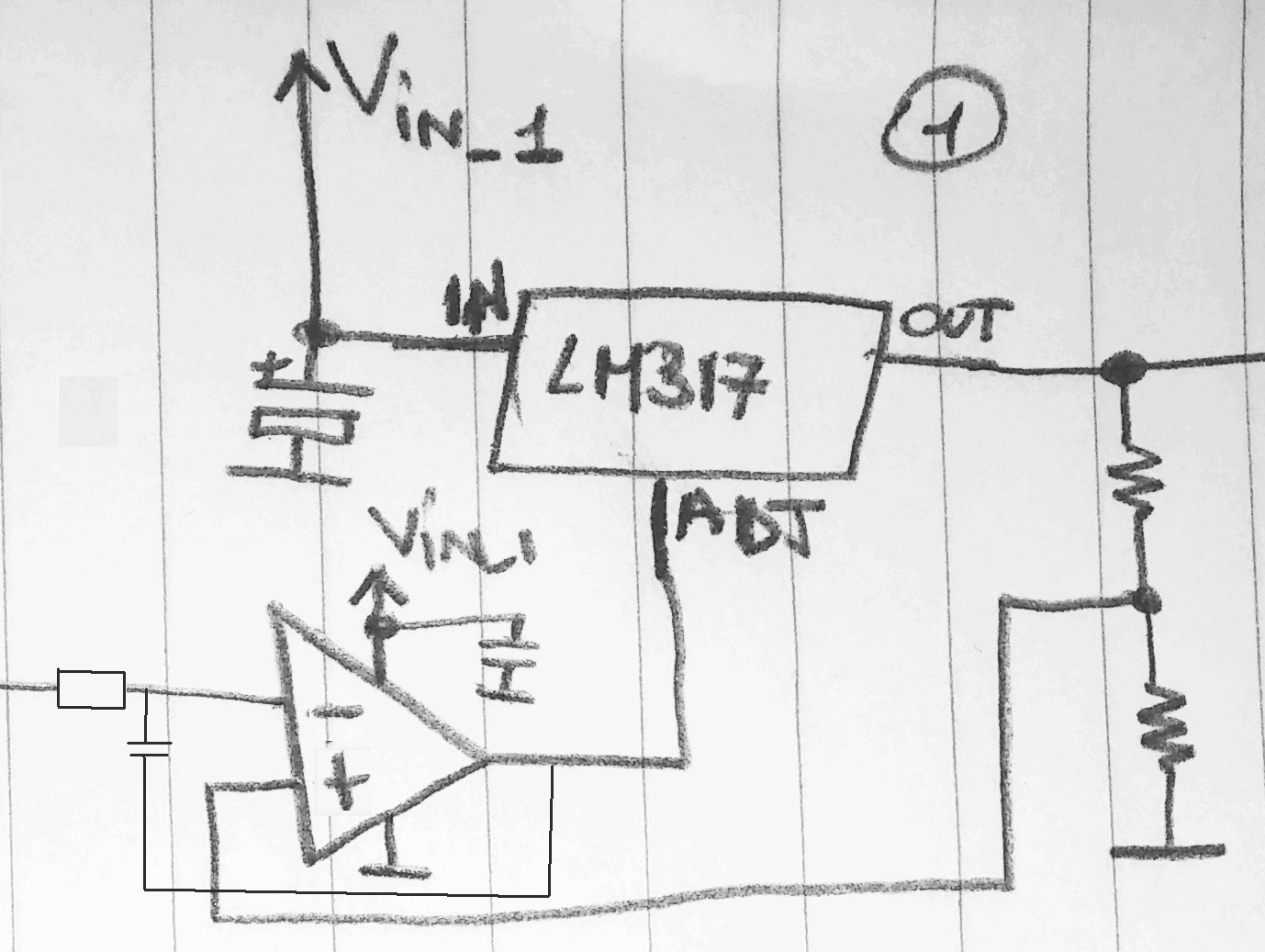
i'm trying to use optocoupler to have variable voltage by lm317 something like this:
asdasdas.jpg
sorry if there is something wrong with the schematic!!
and it's first time i'm using optocouplers! and have no idea how to choose the right one!
how can i choose the right optocoupler?
tnx
 

The purpose of the circuit seems mysterious. The variable resistor should be placed between LM317 Adj pin and ground, without any "optocoupler".

MOC3053 particularly isn't an analog optocpupler rather than an opto triac with zero crossing logic. It surely can't do anything useful in this circuit.

If the circuit is intended as test for isolated control of LM317, you should tell. It could probably use an analog optocoupler, but don't expect a stable and predictable setpoint.
 
actually it should be isolated and as i say i dont know so much about optocoupler so that moc3053 is just a referrer to an optocoupler and the model of optocoupler is my question!!!
the main point is to control 2 of this circuit with one pot! so i have to separate this two circuit with optocoupler!
 

A Triac opto is a phase controlled latch for AC power Triacs. As such they "Latch On with DC" or with AC until next zero crossing.

This DC control will never work and we do not know what output you desire. Vdc range, Imax?

image.jpg
 

tnx for your reply.this schematic is a simple thing that i drew to show what i wanna do to use an optocoupler instead of a pot i dont know the exact circuit and that's what i'm asking. i just wanna know what kind of optocoupler can i use and what is the working circuit? i need that optocoupler work as an pot to make Vout of lm317 different voltages not just like a switch!
 

If you require to control a LM317 with isolation, the simplest way (thought not the most linear) is to use a CdS photocell enclosed in black shrink tubing with a small incandescent lamp.

Photocell-lamp assemblies are also available ready made from several manufacturers, google them.

If you don't require isolation, then avoid using an optocoupler. And certainly not a phototriac one.
 
Optos have very poor CTR tolerance, so no good for precise regulation, without complexity of mirror feedback loop.

That is correct, and that is the reason I warned the OP that it is "the simplest way (thought not the most linear)" and "if you don't require isolation, avoid using a photocoupler".

But, this is one of those threads with very ambiguous requirements, starting with the question: why do you require to use an optocoupler to regulate a LM317 in the first place?
 
the point of isolating the lm317 is to be able to control multiple lm317 with diffrent power sources and loads with one pots.i've searched all over to find 4-gang pots and i found nothing so i have to use one pot. beside i dont know so much about optocouplers maybe the idea if using them for this project was a mistake in first place!(some one told me to use them and gave me nothing else about it)
if anyone has any other idead beside optocoupler it could be good.
tnx so much for your helpful replies.
 

Hi,

to be more linear and equal for both LM317 i recommend to transmit the setpoint as PWM with optocouplers.

As PWM generator you can use a NE555, or ucontroller.
On the output side you need low pass filtering.

1% linearity error should not be a problem.

Klaus
 
Hi!

If you don't want to use uC or digitals, and you want to control multiple LM317 with one pot, you can put for each LM317 the out pin connected to a voltage divider (2 resistors in series), then connect the middle point to the inverting input of an OPAMP, and the out of the opamp to the ADJ pin of the LM317. the out of the pot should be connected to the non-inverting input of all the opamps.

Choose the pot and the opamp in a way that the bias current does not affect the set point of the potentiometer, and that the opamp out can sink the current coming from the ADJ pin. You can also buffer the output of the pot as well.

The schematic you proposed is absolutely not isolated, incredibly non linear, and this means that it doesn't work as you may think. The best way to make it "linear" is to use PWM (as suggested by KlausST).
 
Hi,

to be more linear and equal for both LM317 i recommend to transmit the setpoint as PWM with optocouplers.

As PWM generator you can use a NE555, or ucontroller.
On the output side you need low pass filtering.

1% linearity error should not be a problem.

Klaus

Hi!

If you don't want to use uC or digitals, and you want to control multiple LM317 with one pot, you can put for each LM317 the out pin connected to a voltage divider (2 resistors in series), then connect the middle point to the inverting input of an OPAMP, and the out of the opamp to the ADJ pin of the LM317. the out of the pot should be connected to the non-inverting input of all the opamps.

Choose the pot and the opamp in a way that the bias current does not affect the set point of the potentiometer, and that the opamp out can sink the current coming from the ADJ pin. You can also buffer the output of the pot as well.

The schematic you proposed is absolutely not isolated, incredibly non linear, and this means that it doesn't work as you may think. The best way to make it "linear" is to use PWM (as suggested by KlausST).

i will consider your ideas but could you tell me more details? or maybe a schematic?
i saw this on lm317 datasheet can i do that? does it work with 3 separate power sources and loads with connected power sources grounds together?
tnx
 

**broken link removed**
As you can see from the picture it a very basic, simple schematic...

Some adjustments should be done, depending on the components that you want to use, precision...

if something is not clear, or you think that is wrong, please ask :)
 

**broken link removed**
As you can see from the picture it a very basic, simple schematic...

Some adjustments should be done, depending on the components that you want to use, precision...

if something is not clear, or you think that is wrong, please ask :)

sorry man but i think there is something wrong with the attachment!
 

20141028_222820.jpg

Sorry :)
 
  • Like
Reactions: FvM

    FvM

    Points: 2
    Helpful Answer Positive Rating
As you can see from the picture it a very basic, simple schematic...
But unfortunately not working. The fact that it's inverting the polarity of LM317 feedback should be a sufficient indicator.

Flipping the OP inputs could fix the polarity problem. But then excessive LM317 feedback gain will cause instability, you need to add a compensation network.

- - - Updated - - -

This correction might work


My usual solution would be to feed the (inverted and scaled) control voltage to the bottom node of each LM317 voltage divider.
 

Hi!

I'm pretty sure that the feedback polarity is not inverted, because if you look at the internal schematic of the LM317 in the datasheet, and you follow the path of the ADJ pin into the multiple stages, you will find out that the increase in voltage of the ADJ pin causes an increase in the driving current of the darlington pair used as pass transistor. In the end, it maintains the voltage between ADJ and OUT constant. This means that in your schematic if Vout increase (with constant position of the pot), the out of the opamp increase, increasing Vadj and so increasing Vout, in a positive feedback.

I checked in a spice simulation and the polarity seems correct.

By the way, I totally agree with the fact that some compensation probably should be done in order to increase stability of the circuit, whenever it shows phase margin issues.
 
  • Like
Reactions: FvM

    FvM

    Points: 2
    Helpful Answer Positive Rating
Yes, you are right about polarity. I didn't consider that the LM317 Adj. voltage is acting relative to the output node. The stability problem exists nevertheless. In so far a circuit that doesn't add gain to the LM317 feedback still seems preferable.
 

I'm absolutely with FvM on this one. Adding gain to any feedback path, without proper loop analysis and stabilization, is a recipe for disaster.

The circuit can break into oscillation at any time.
 

Status
Not open for further replies.

Similar threads

Part and Inventory Search

Welcome to EDABoard.com

Sponsor

Back
Top