Vermes
Advanced Member level 4
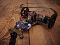
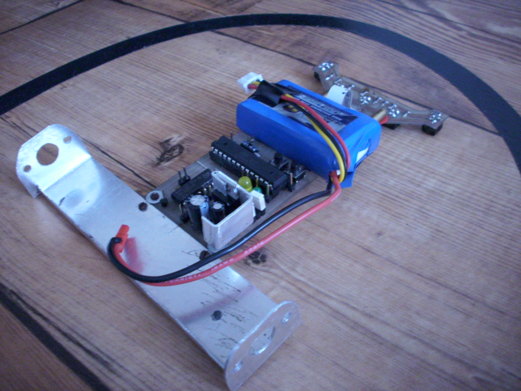
The electronics are based on two boards:
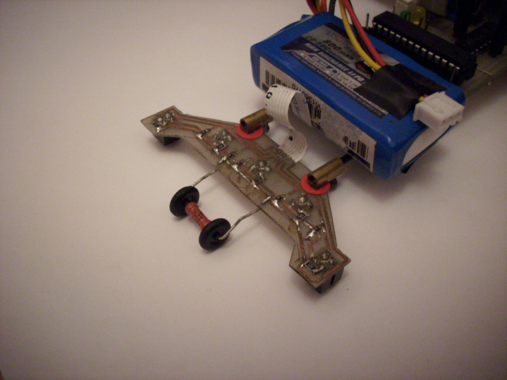
- the board with sensors, powering diodes and pull-up resistors.
- after powering by 5V (stabilized), it returns analog signals
- 5 x CNY70 sensors
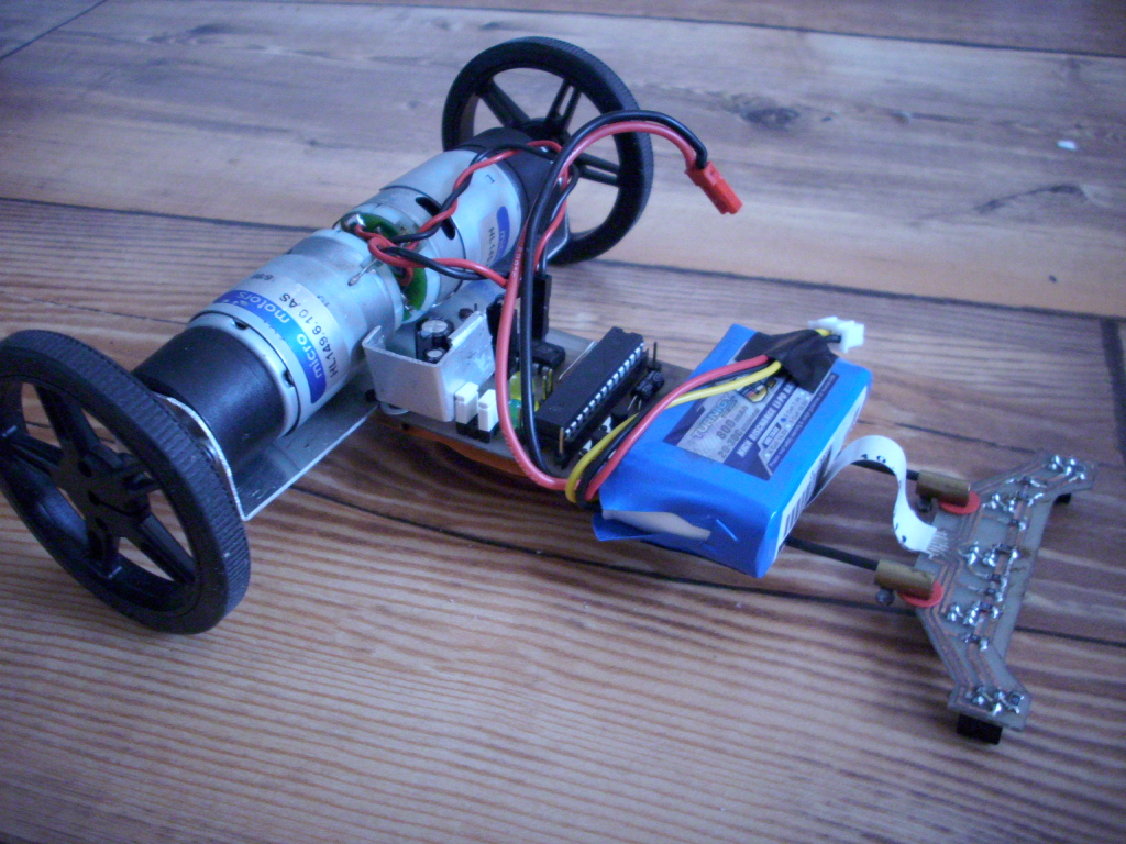
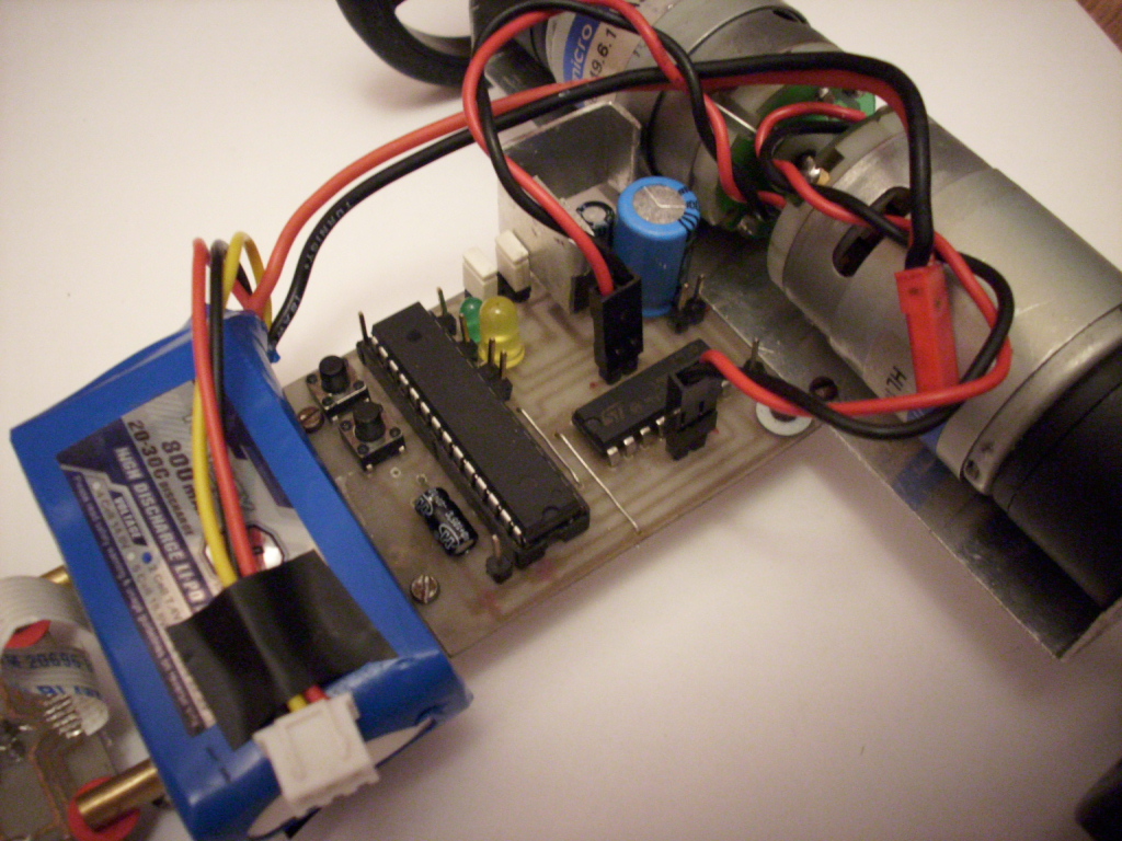
- microcontroller board with power supply and H bridges to steer the motors.
- the main chip: Atmega8 in dip housing
- l293d bridge
The electronics were designed to be useful in other robots like minisumo robots, easy step mechanics. There are 7 I/O pins to connect: an external quartz, timer 2, connecting servos, adding a fifth ADC channel. Additionally, there are some soldered places on the board to build in a tension divider. There can be found also: 2 diodes, two switches and power supply exits 5V, GND and VCC for supplying external devices. To the Aref output, a capacitor or potentiometer can be connected to change the reference voltage.
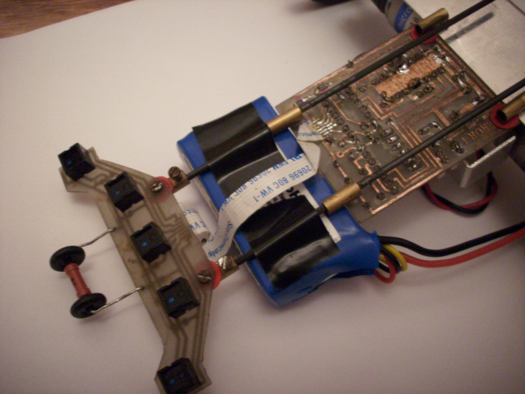
The boards are connected by tape (power supply and signal from sensors) and two coal rods (fi 2mm) mounted on sleeves removed from electrical cubes. This type of connection enables to adjust the position of the board with sensors in any axis and any direction, furthermore, it is very solid and very light – 25g.
The robot is powered from a Li-Pol battery – 2S 0,8Ah (in the second edition 3S)
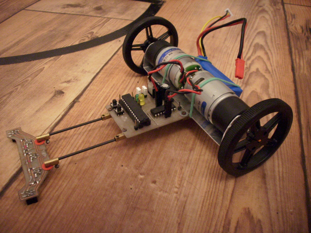
The drive is based on motors with gears (micromotors company – hl149) with some modifications:
- plastic gears were replaced with metal ones
- the motors were shortened and lightened – the rear covers were thrown away, and the rear rollers were shortened
- 4mm “D” rollers sawn to 3mm
- replaced connectors to goldpins
- overvoltaging – the motors should be powered by 6V, they are powered from 3S
Software: based on P regulator, but in the near future it will be changed to PD or PID

The first start:
Link to video:
Route “0”:
Link to video:
One round is 2m – time needed about 3,5s (speed counted 0,6m/2). In new software, it takes about 2,8s.
Route “0” - 2m:
Link to video:
10 meter test:
Link to video:
Average speed 0,7m/2 – 15cm/s
Link to original thread (addition with hex, PCB, schema, etc.) – Robot klasy linefollower "ERROR1"