Continue to Site

Welcome to EDAboard.com

Welcome to our site! EDAboard.com is an international Electronics Discussion Forum focused on EDA software, circuits, schematics, books, theory, papers, asic, pld, 8051, DSP, Network, RF, Analog Design, PCB, Service Manuals... and a whole lot more! To participate you need to register. Registration is free. Click here to register now.

[SOLVED] limiting integrator in veriloga

Status
Not open for further replies.

Nixphe

Junior Member level 1
Joined
Aug 17, 2010
Messages
17
Helped
0
Reputation
0
Reaction score
0
Trophy points
1,281
Location
BE
Activity points
1,449
Hello,


I tried to make an integrator in veriloga. Using the idt function (out = idt(in, 0);), this is very easy. Then i wanted to limit the integrator to 0V at the lower side and to 1V at the upper side. This proved to be a lot harder than i thought.

I had:
out = idt(in, 0);
out = (out>1)? 1:eek:ut;
out = (out<0)? 0:eek:ut;

The limiting part works, but apparently clipping variable "out", does not clip the integral.

Then I started experimenting with 2 things, one is the assert option, the other is to change the "in" variable when out of range, i.e.:
if ( ((out>1)&&(in>0)) || ((out<0)&&(in<0) )
in = 0;
out = idt(in, 0);
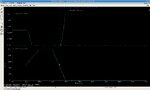
This kind of works. I expected the output to go little over the boundaries, but i was quite surprised to see out rising up to 1.5 or even 2.

How can i solve this? What's the reason of this problem?

Thanks in advance!
 

Hi, Nixphe.
The following code implement function you need

// VerilogA for edaboard, integrator, veriloga

`include "constants.vams"
`include "disciplines.vams"

module integrator(in,out,gnd);
input in;
output out;
inout gnd;
electrical in,out, gnd;

parameter real cap = 10n from (0:inf);
real x;
analog begin
x = 1/cap*idt(V(in),0);
if (x>=1) x = 1;
if (x<=0) x = 0;

V(out)<+ x;

end

endmodule


Regards.
 
  • Like
Reactions: Nixphe

    Nixphe

    Points: 2
    Helpful Answer Positive Rating
Hello,

thanks for your reply.

I tried this implementation before asking for help but it doesn't work. The output is clipped to some max and min indeed, but the integration function seems to work with some internal variable which is not clipped. Imagine i apply some positive voltage. Output rises and clips at Vmax. Only after a while I apply a negative input voltage. In a real clipped integrator, the output voltage would drop immediately. Though in this implementation internally the integrator is well beyond Vmax and the output remains clipped at Vmax till internally the integrator goes below Vmax. This is not the desired operation. I hope my explanation makes sense and is clear :)

Any suggestions?
 

but the integration function seems to work with some internal variable which is not clipped
Yes, that the nature of an integrator function. Personally, I would design a limiting integrator on my own, but I'm not familiar with Verilog A to suggest a detail solution.

i was quite surprised to see out rising up to 1.5 or even 2
I guess, that's a problem of the simulation timestep. The latter can probably be adjusted. In any case, I would provide a negative feedback to implement the limiting function instead of only disconnecting the input signal. I've used similar constructs for analog behavioural simulations in SPICE.

I'm not sure how Verilog A exactly works, but analog simulators generally prefer continual circuit equations to abrupt discontinuities.
 
  • Like
Reactions: Nixphe

    Nixphe

    Points: 2
    Helpful Answer Positive Rating
Thanks for your input!

Yes, that the nature of an integrator function. Personally, I would design a limiting integrator on my own, but I'm not familiar with Verilog A to suggest a detail solution.

I'm not very familiar with verilog A neither, I have no idea how to do this. If someone would have a suggestion, this would be greatly appreciated

I guess, that's a problem of the simulation timestep. The latter can probably be adjusted. In any case, I would provide a negative feedback to implement the limiting function instead of only disconnecting the input signal. I've used similar constructs for analog behavioural simulations in SPICE.

I'm not sure how Verilog A exactly works, but analog simulators generally prefer continual circuit equations to abrupt discontinuities.

Verilog doesn't like abrupt discontinuities neither, Verilog A is interpreted by Spectre here. Normally one could give options to the integrating function to change the timestep, but these "are not supported in the current Verilog A release". And making the timestep of my entire system very small would lead to long simulation times
 

Verilog doesn't like abrupt discontinuities neither, Verilog A is interpreted by Spectre here. Normally one could give options to the integrating function to change the timestep, but these "are not supported in the current Verilog A release". And making the timestep of my entire system very small would lead to long simulation times
That's why I think the negative feedback idea is promising:
Code:
if (out>1) in = 1 - out;
else if (out<0) in = -out;
out = idt(in, 0);
 
  • Like
Reactions: Nixphe

    Nixphe

    Points: 2
    Helpful Answer Positive Rating
Hi, Nixphe.
You gave really good explanation:grin:
Here are VerilogA code which models integrator realized using ideal opamp with gain 1e+6 and output voltage from -1 to 1. You can adjust time integration constant by changing either parameters res or cap.

// VerilogA for edaboard, integrator, veriloga

`include "constants.vams"
`include "disciplines.vams"

module integrator(in,out,gnd);
input in;
output out;
inout gnd;
electrical in,out,gnd,inn;

parameter real cap = 1p from (0:inf);
parameter real res = 10k from (0:inf);
parameter real lim = 1 from (0:inf);

real inv,outv,gain;
analog begin
@(initial_step or initial_step("dc")) begin
gain = 1e+6;
end

I(in,inn)<+V(in,inn)/res;
inv= V(inn,gnd);

outv = -gain*inv;
if(abs(outv)>lim) outv = lim*outv/abs(outv);


V(out,gnd)<+ outv;
I(inn,out)<+cap*ddt(V(inn,out));

end

endmodule


as you can see, there are some delay (10.2ns) between input voltage becomes negative and output begins to rise from -1V. This is connected with the fact that when integrator in saturation, input voltage of opamp doesn't equal 0 - so it demands some time to charge capacitor. You can decrease cap and increase res (so their product will remain the same), to iluminate this phenomenon.
Regards.
 

Attachments

  • timing.jpg
    timing.jpg
    217.1 KB · Views: 191
  • Like
Reactions: Nixphe

    Nixphe

    Points: 2
    Helpful Answer Positive Rating
Thanks for all the replies. Pavel's solution works as a dream :)
 

Status
Not open for further replies.

Part and Inventory Search

Welcome to EDABoard.com

Sponsor

Back
Top