Continue to Site

Welcome to EDAboard.com

Welcome to our site! EDAboard.com is an international Electronics Discussion Forum focused on EDA software, circuits, schematics, books, theory, papers, asic, pld, 8051, DSP, Network, RF, Analog Design, PCB, Service Manuals... and a whole lot more! To participate you need to register. Registration is free. Click here to register now.

LED Matrix Display Hardware Design Help

Status
Not open for further replies.
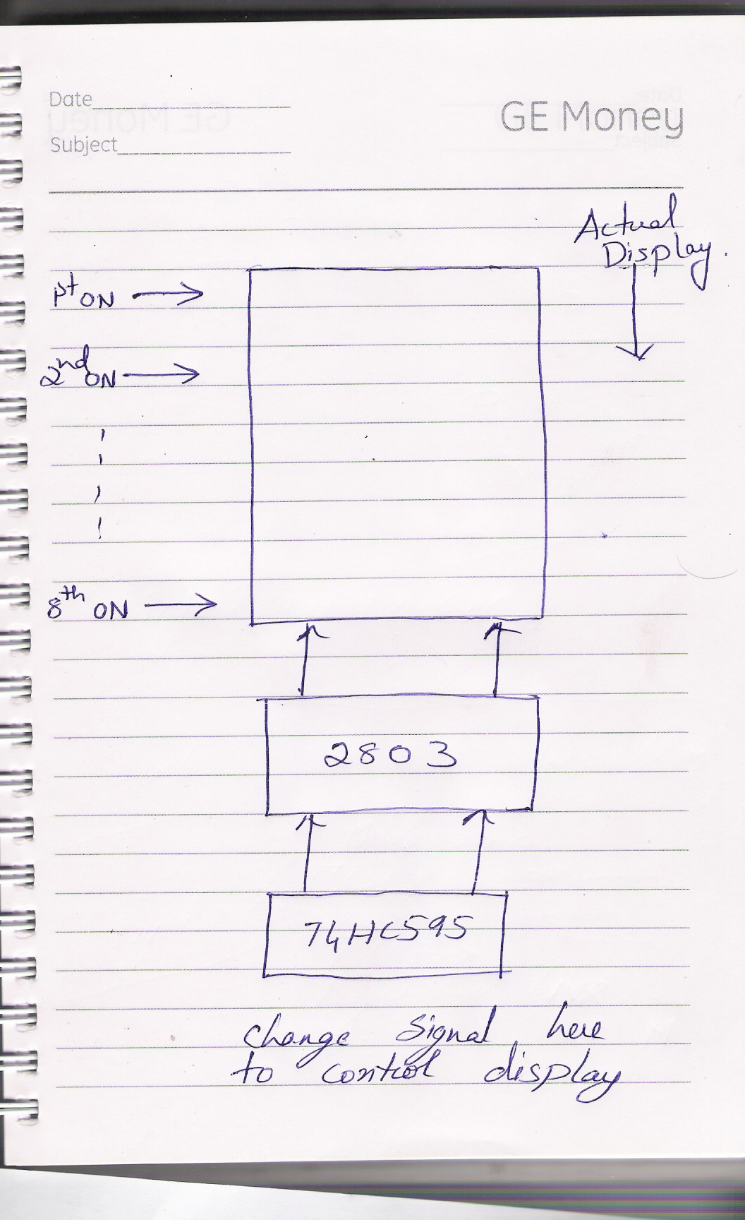
What king of multiplexing are you doing because the way that the circuit is wired I would expect to turn on

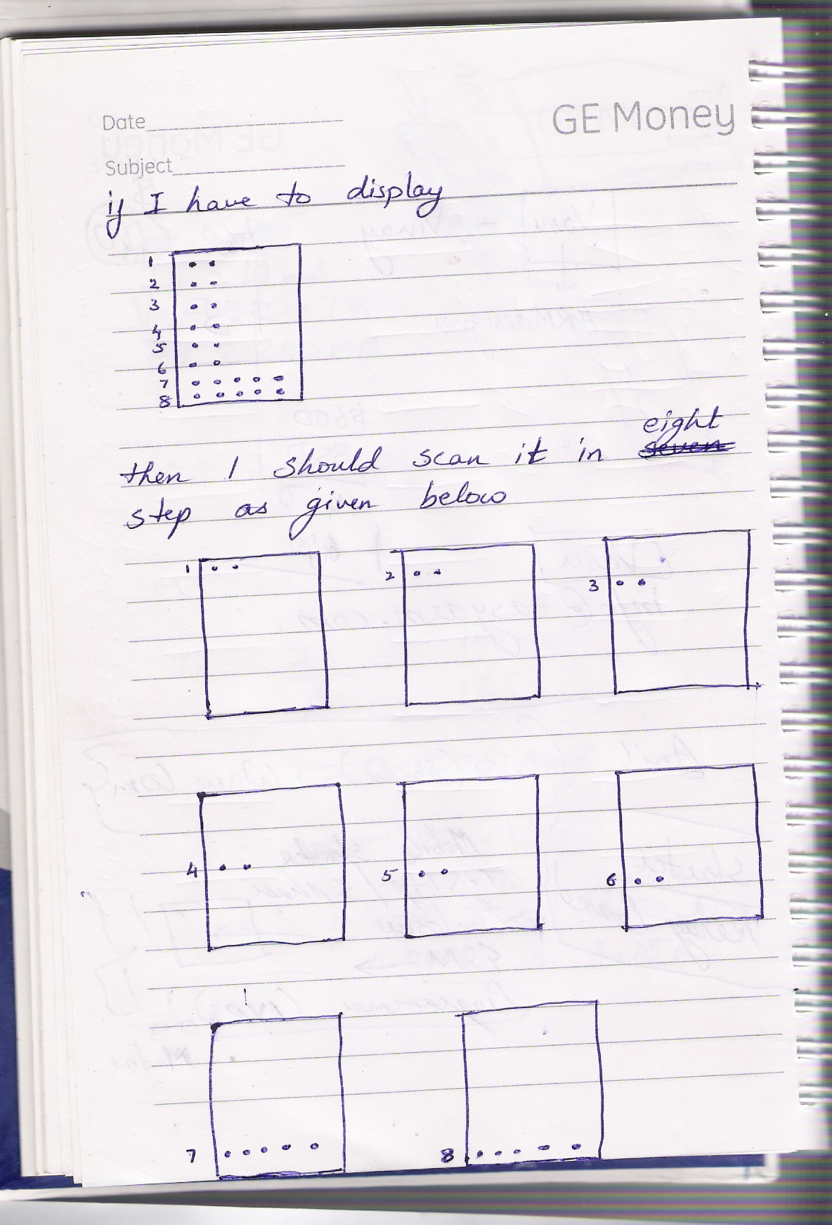
Row1 (and all columns of all display)
Row2
Row3
Row4
Row5
Row6
Row7
Row8
and then again from row 1


What you describe is
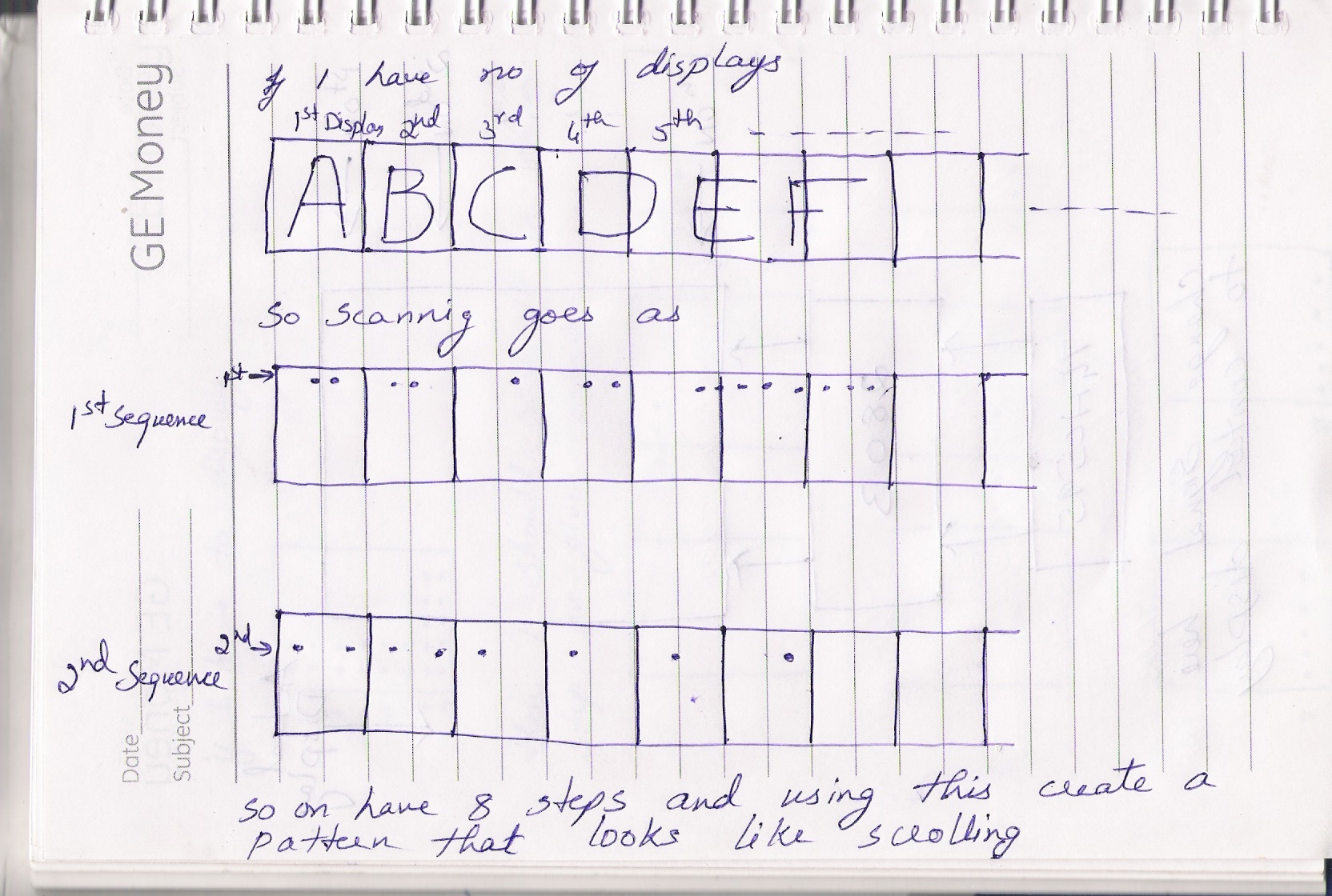
turn on all row/column of display 1
turn on all row/column of display 2
turn on all row/column of display 3
turn on all row/column of display 4
turn on all row/column of display 5
turn on all row/column of display 6
turn on all row/column of display 7
turn on all row/column of display 8
and then from start

This way you need a faster multiplexing rate 1/16 but less current, in the first way you need lower rate 1/8 and higher current, it is up to you but I don't understand why did you use the individual anode transistors if you are going to turn on/off all 8 of them at the same time(the second way)?

Alex
 

Practically do a test in order to find the LEDs current value producing the light intensity you need, and later for the multiplexed display use a current pulse 8 times higher this value.
 

Practically do a test in order to find the LEDs current value producing the light intensity you need, and later for the multiplexed display use a current pulse 8 times higher this value.

I have only used this with a 7 segment display but I have used the same 220 ohm resistors as with DC and the output was fine, I only had dimmed output with high frequency when I tried to multiplex every single segment instead of multiplexing each display.

What you are saying is if a 220ohm resistor provides 10mA in a led then for 8 leds multiplexed we should use 220ohm/8?
And should we do that irrelevant from the multiplexing frequency?
It can be 8Hz, or 80Hz or 400Hz , do you use the same calculation for any frequency?

Alex
 

Four years ago, I launched a new series of moving message sign mainly for outdoor. Reliability and simplicity were the most concerned.
The LED type I used is the red bright one rated @20mA (the number of LEDs in one pixel depends on sign size).
I decided to drive the LEDs with a DC current (in the range of 15 to 20mA) when an LED is on during the frame period.
This was possible by cascading "16-bit Constant Current LED Sink Driver" ICs. The Chinese factory which produced my modules suggested MBI5026 (made in China but it turned out be a good one).
The interface of these driver ICs is made compatible to SPI (serial peripheral interface) which my available Atmel AT89C8252, AT89C8253 and SST89E58RDA uC have.
At a rate of 30 frames/sec, up to 4096 LEDs could be refreshed (though my software is not yet optimized).

It is just an idea.

Kerim

Off topic:
I designed my first moving sign in 1979. Its pixel was 40W 220Vac bulb driven by a triac. Its controller was made using Z80 and 27C512 EPROM.
Soon later, my first LED sign was 64 x 7 based on scanning (also for Arabic messages for which I create a special font that needs only 7-pixel height). The LED was pulsed with 400mA! The duty cycle was 1/64. Although these small signs lived for many years, I won't do again now :) In fact, the static mode lets the design be rather simple, flexible and reliable. So while most of my last series signs usually run 24/7, some of them are 4 years old now :)
 
Last edited:

...What you are saying is if a 220ohm resistor provides 10mA in a led then for 8 leds multiplexed we should use 220ohm/8?
In theory yes, in practice no, :grin: as the efficiency of an LED typically rises with forward current, presuming constant junction temperature, (but this is not always the case however), and LED data sheets should be examined when choose the optimum peak current.
Also we have an advantage that the human eye is responsive to the peak value of illumination. The attack time is significantly shorter than the release time, making the eye tend to be a peak sensing device rather than an photometer detector. That’s why the eye perceives rapidly pulsed light, somewhere between the peak and the average brightness (works better on blue & green than it does on red LEDs.) This means that for a low duty cycle high intensity pulse of light looks brighter than a DC signal equal to the average of the pulsed signal.
 
  • Like
Reactions: KerimF

    KerimF

    Points: 2
    Helpful Answer Positive Rating
[/COLOR]
How did you calculate the 7 x 96 and 16x96? The schematic has 15 displays 8x5 each Assuming that the multiplexing is done using the transistors in the 8 anodes (row 1,2,3...8,1,2,3...) then the max consumption can be one row on in all 15 display so 15*5=75*10mA=750mA ..Alex
Sorry for the confusion. But when the op was refering to DC consumption of the LED's i was putting up practical calculations of different models what i have with me.
Cheers
 

Hello everyone

I have attached a few images which might give you a detail on what i am trying to do right now. As you can see in the image, I have not used any IC or transistor to drive anodes (I will do this later for sure) instead i have connected all anode to Vcc (+5v) via 330ohm resistor. When all the LEDs go ON, 7805 starts to heat slowly.

Controller has not been connected yet.

The cathode are run via 74HC595 followed by ULN2803.

I dont see current being a problem but I also know that it might actually be the issue. Confusing...

Also attached is a video for your reference. Here is the link.

‪Single 8X5 LED Display.MP4‬‏ - YouTube
 

Attachments

  • Copy of DSCF5535.JPG
    Copy of DSCF5535.JPG
    2 MB · Views: 59
  • Copy of DSCF5536.JPG
    Copy of DSCF5536.JPG
    1.9 MB · Views: 60
  • Copy of DSCF5537.JPG
    Copy of DSCF5537.JPG
    2 MB · Views: 62

.... I have not used any IC or transistor to drive anodes (I will do this later for sure) instead i have connected all anode to Vcc (+5v) via 330ohm resistor. When all the LEDs go ON, 7805 starts to heat slowly. Controller has not been connected yet.
The cathode are run via 74HC595 followed by ULN2803.

Hi tiwari.sachin;

Your experiment above is NOT a multiplexing circuit, so when all leds go on, the sum current is about 400 mA (10 mA x 8 x 5). Your power supply (as you wrote) is 9 v, so the 7805 is dissipating about 1.6 Watt ((9 - 5) Volt x 0.4 Amper), without any heatsink it will be very hot.

Use the row scanning multiplexing method:
Only one row (in this case 5 leds) switched on at a time, so the max current will be 50 mA in case of one 8x5 led matrix (or 800 mA in case of 16 led matrices). Do it (the row switching) fast enough to prevent any flickering. A 100 Hz rate is enough.
I recommended the increasing the led currents to 20 or 30 mA (determined with the current limiting resistors at the cathode side) for a well brightness. So the max current will be 1.6 or 2.4 A, but you have a 3 A supply.
Do not forget to apply a big heatsink for the 7805, or modify your circuit to supply the led anodes (via the PNP power transistors, 8 pcs) inmediately from the input voltage.
 
Last edited:
@zuisti

Thanks for that explanation.
I have attached a pictorial view to clarify about the understanding.

I was trying to do it the otherway round and that probably would have had flickering effects. Your option seems more reasonable and a better design especially when 74HC595 can source only 30mA. It surely needs a lot of programming though.

Meanwhile, i have kept a single matrix ON (all LEDs as shown in figure before this post) for the entire day today and the 7805 didnot heat any further. Seems i will have to think about some power dissipation factors here because the final product will have more such matrix displays connected.

As far as PNP goes, TIP 127 should be fine. Do you have any other suggestions?


Seems like everyone has stopped replying. guys... kindly let me know if i am following it right...
 

So if you will have 8 matrices (each 5x8), your pnp (or P-MOS) transistor will drive 8 * 5 = 40 LEDs (duty cycle 1/8).
I think you will write your first software to test 1 matrix so you can check the display brightness for the LED current you decided on.
When you will add more matrices, the only difference you will notice is that the voltage drop on the anode driver will increase which in turn may decrease a bit the LED's brightness (assuming your supply has enough power).

Kerim
 

Status
Not open for further replies.

Part and Inventory Search

Welcome to EDABoard.com

Sponsor

Back
Top