Continue to Site

Welcome to EDAboard.com

Welcome to our site! EDAboard.com is an international Electronics Discussion Forum focused on EDA software, circuits, schematics, books, theory, papers, asic, pld, 8051, DSP, Network, RF, Analog Design, PCB, Service Manuals... and a whole lot more! To participate you need to register. Registration is free. Click here to register now.

LED Matrix Display Hardware Design Help

Status
Not open for further replies.

tiwari.sachin

Full Member level 6
Joined
Aug 1, 2009
Messages
341
Helped
3
Reputation
6
Reaction score
3
Trophy points
1,298
Location
India
Activity points
4,449
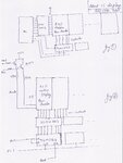
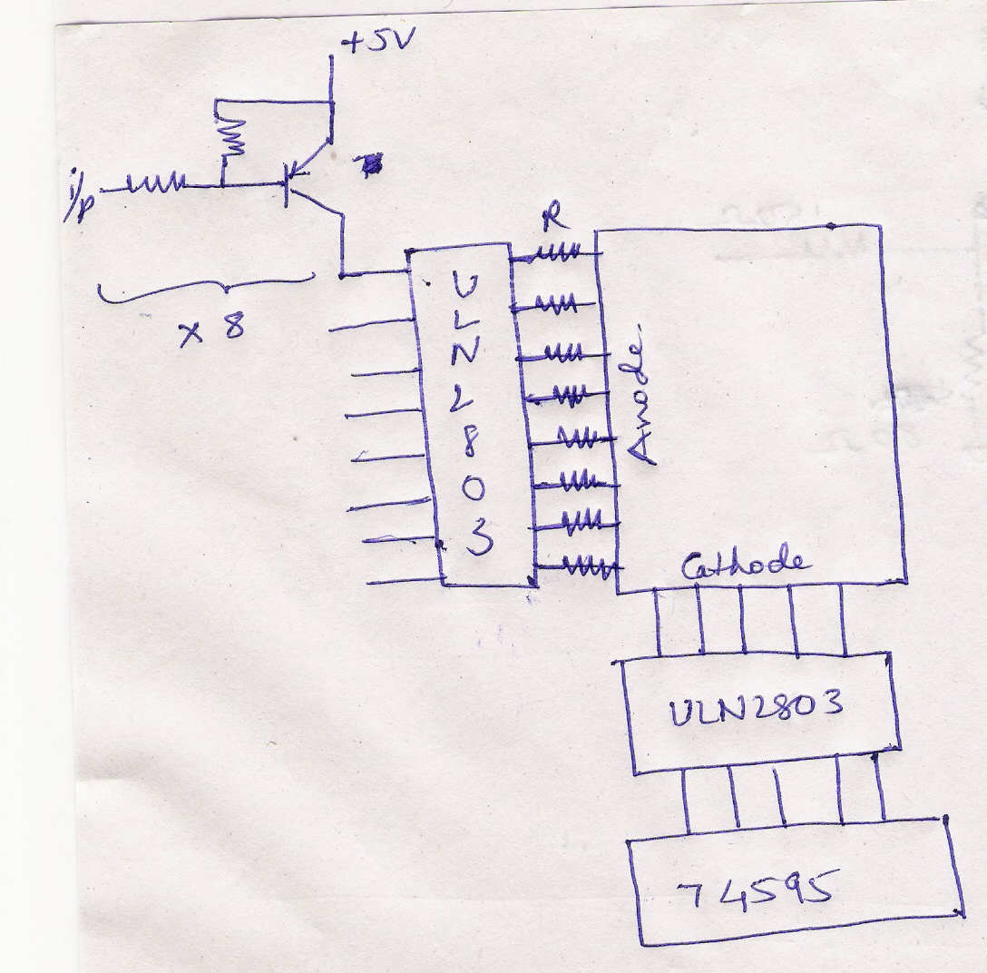
I am trying to design a matrix LED display using 5x8 ROW Anode display. I am not sure but i might be using 15 to 16 such displays for the initial version(ofcourse this can change as per customers requirement)

What seemed easy initially seems way too confusing now. I am not able to understand which are the appropriate ICs that i should go in for the design.

I have attached two possible design configurations for your reference. Kindly let me know which one is more feasible option. Or might be even a third option :)

I was initially told to use 74HC595 but i am not too convinced with it. I am not sure if it can handle the amount of current flow in worst, all LED ON condition.

I will surely not be driving all the LEDs at a time but then if its done, the hardware should not blow :) I want to surely have a very decent reliable hardware design.

Meanwhile, the controller used will be LPC2148.

Waiting for your response.
 

Attachments

  • 2 Configurations.jpg
    2 Configurations.jpg
    886.4 KB · Views: 234

What is the reason for going for such a high end controller... you can do it on 8 bit controller.. there is a blog too on this topic. and if you search the forum.. you get many answers.........
 

I have searched it and couldnt find more solid answer. The reason for using LPC2148, well... I have different font types that it should handle, a QWERTY Keyboard interface, Real Time Clock, around a lakh message storage capacity (achieving it using a SDCard) and each message about a 1000 character wide and a little more features. And possibility to edit each of them.. well takes in a lot of programming and performance. so as you can see there is a lot of work involved..

Coming back to the hardware. I dont have much details about the LED Matrix part number but it has CPM23058 AURD 2/A written on it. Since its a red color LED, i am guessing that the voltage drop will be 1.8V and requires about 20mA. Correct me if i am wrong.

So if all the LEDs are ON, the current required will be 20mA x 600 (LEDs approx) = 12 amp

Power dissipated by LEDs (when all ON) = 20mA x 5V x 600 LEDs = 60 Watts

Thats way too much. so just wondering what might be the possible solution.

As I have already told, there can be a increase in number of displays later so the current and power dissipation can still increase. But as for now its 600 LEDs
 

As it matrix design and there is no possibility of all the LED's ON at an instance. Maximum of 5x16 LED's will light up at an instance if you are using row scanning. Calculate the power needed.
 

Model: CPM23058

Emitting dot: 3.0mm diameter
•High luminous intensity output
•High efficiency
•Low power consumption
•Extremely low current
•Luminous evenly distributed on each segment
•Emitting color: various
•Dominant wavelength & Luminous intensity & Forward voltage:
Blue:460nm 50mcd 3.5V,
Pure green:515nm 180mcd 3.5V,
Green: 565nm 13mcd 2.2V
Yellow: 590nm 50mcd 2V,
Amber:605nm 30mcd 2V,
Super-bright red: 625nm 80mcd 2V
Orange: 630nm 30mcd 2V,
Red: 645nm 10mcd 1.85
Reverse voltage: 5V
Recommend use current/segment: 5 to 10mA

Good brightness can be had with as little as 5mA to 10mA average current for each LED. This requires 40mA to 80mA peak current for a 12.5% duty cycle / one digit, and for the total of 15*5=75 LEDs -> I= 75* 80mA = 6000mA= 6A :cool:
 

The reason for using LPC2148, well... I have different font types that it should handle, a QWERTY Keyboard interface, Real Time Clock, around a lakh message storage capacity (achieving it using a SDCard) and each message about a 1000 character wide and a little more features. And possibility to edit each of them.. well takes in a lot of programming and performance. so as you can see there is a lot of work involved..
So if all the LEDs are ON, the current required will be 20mA x 600 (LEDs approx) = 12 amp. Power dissipated by LEDs (when all ON) = 20mA x 5V x 600 LEDs = 60 Watts Thats way too much. so just wondering what might be the possible solution. As I have already told, there can be a increase in number of displays later so the current and power dissipation can still increase. But as for now its 600 LEDs
First of all who will expect a viewer to see all the messages having a MMD with 1 lakh messages? Next is using a qwerty keboard is the same which is used with desktops with a PS2 or a USB connector which can be driven evven by a Philips 89C52RD2 or Atmega32 or similar including driving of various fonts too. BTW the DC power consumed by a 7x96 MMD will be hardly 800Ma @ 5volts.
 

@mister_rf.

Thanks for the details on the display. It would surely be very helpful. Meanwhile I also think that there will be losses at resistors too so that probably might waste a bit of energy in there. Will post the details once i have the detailed solution ready.

I was initially trying out using a 7805 to drive a single display to see how it would respond. With all LEDs ON, 7805 tends to start heating so there are some issues for sure. Any suggestions on this?

Meanwhile How can i drive the anode part. I was thinking of using a pnp for each row.

@pranam77

Agree to what you say. 1lakh msg, who gonna store them anyways but then thats the requirement.

LPC2148 and Atmega32.. theres hardly any price difference. We have all the IDE and debugging tools for LPC ready then why ATMEGA and start everything from scratch.

Everyone has there own reasons for selecting a specific controller. There are other options too and i completely agree to that.
 

74HC595 can provide a current of up to +-35mA, this is clearly not enough in your case because even if a single column turn on you will need more than that (assume that all leds of the column turn on).

You can either use discrete transistors to drive the leds or ULN2003/2803 to drive the cathodes and UDN2981 to drive the anodes

Alex
 
"UDN2981 to drive the anodes"

I tried to find but this part is not available here.

To drive cathode, i would be using a shift register (74HC595) followed by ULN2803 for each cathode line.

I am still thinking about what to use for driving anode. especially with such power hungry LEDs (rather group of LEDs)
 

You can simply use individual transistors to drive the anodes, it shouldn't be a problem.
If you want to drive them with low currents you can use darlingtons

Alex
 

Any suggestions of this

TIP127 along with ULN2803 for anode (Do I actually need ULN here)
74595 with ULN2803 for cathode

I have attached a reference block as a attachment


TIP127 along with ULN2803 for anode (Do I actually need ULN here)

Apart from the fact that there is no reason to use a ULN between the transistors and the anodes there is also the problem that ULN2003/2803 have open collector outputs so they can't source current (drive the anodes), they can only sink current (drive the cathodes)

Alex
 

alexan,

a valid point that i missed.

As posted before, I was trying to drive a single matrix display as for now by using a 74HC595 and ULN2803 for cathode and TIP127 for driving anode.

I am using a PIC16F873 for testing single display.

For power I am using a 7805 which can give upto 1 amp.

I find that the total current required considering each LED will consume 10mA, would be 8 X 5 X 10mA and should not go beyond 400mA but i find that 7805 starts heating when i switch on the LEDs.

I am unable to find the reason behind it. Can you give me some suggestions on the same. Input to the 7805 is a 9v/3amp adapter
 

As in practical, the led's are multiplexed and do not take the actual current as it runs on a DC voltage. Thus the consumption of a 7 x 96 MMd is arround 800Ma @5 volts and 16 x 96 is 1600Ma. Instead using the 7805, you get 5 volts 2A SMPS plug in power supplies for arround 300/- rupees.
Cheers
 

The power consumption on the 7805 is 4v*current so it depends on the total current of your circuit, not just the leds.
Maybe total current is higher.

Alex

---------- Post added at 15:33 ---------- Previous post was at 15:22 ----------

As in practical, the led's are multiplexed and do not take the actual current as it runs on a DC voltage. Thus the consumption of a 7 x 96 MMd is arround 800Ma @5 volts and 16 x 96 is 1600Ma. Instead using the 7805, you get 5 volts 2A SMPS plug in power supplies for arround 300/- rupees.
Cheers

How did you calculate the 7 x 96 and 16x96?

The schematic has 15 displays 8x5 each
Assuming that the multiplexing is done using the transistors in the 8 anodes (row 1,2,3...8,1,2,3...) then the max consumption can be one row on in all 15 display so 15*5=75*10mA=750mA

Alex
 
Don’t forget since we have a multiplexed display, the total light intensity produced by the LEDs need to be compensated, as each LEDs row run on power for 1/8 time period. A pulse of 10mA = 1.25mA normal current.
 

sorry, I don't get that, when you have 8 leds (eight rows of one column) and each one of them consumes 10mA and you do multiplexing (row 1,2,3...1...)then the consumption will still be 10mA because in any given moment one of the 8 leds will be on, in other words 1/8 of the 80mA which is 10mA per column

Alex

---------- Post added at 16:14 ---------- Previous post was at 16:06 ----------

I think you meant the light intensity but if the multiplexing speed in not high (like 400Hz for 50Hz*8) there shouldn't be a reduced light output problem
 

Here we have a situation similar to pulse width modulation, controlling the pulse width and duty cycle, causing the LED light to vary its intensity. As the LED will remain off even longer we produce an increased dimming effect.
 

@pranam77
7 x 96 MMd is arround 800Ma @5 volts and 16 x 96 is 1600Ma. How did you get this. I thought of first trying a single 8x5 display unit. I was talking about only one unit right now. Later the board will have additional display units.

Kindly eloborate "the led's are multiplexed and do not take the actual current as it runs on a DC voltage."


@Alex

Ofcourse the cureent will be the total current of the entire circuit. I havent even loaded the controller and 75HC595. I have just connected the IC base and left it open.
so according to the theory it will be

total LEDS x Current consumed by them
In this case (8x5) LEDs multiplied by 10mA = 400mA. This is something 7805 can supply easily.
 

Status
Not open for further replies.

Part and Inventory Search

Welcome to EDABoard.com

Sponsor

Back
Top