ArticCynda
Advanced Member level 1

- Joined
- May 8, 2013
- Messages
- 439
- Helped
- 82
- Reputation
- 164
- Reaction score
- 81
- Trophy points
- 1,308
- Activity points
- 4,238
Hi everyone,
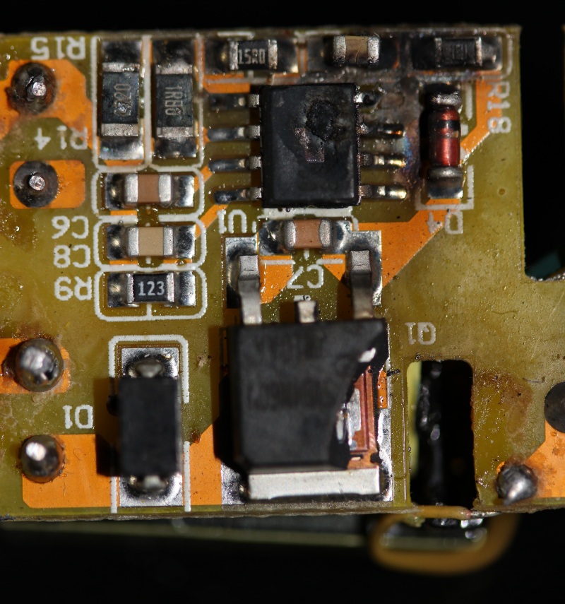
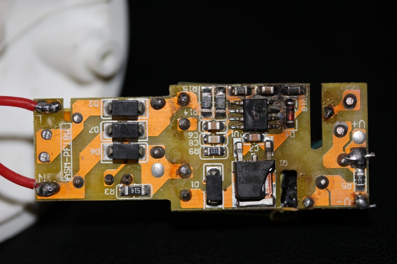
I'd like to fix a burned out driver circuit for a 30W (15 x 2W) LED lamp, photographs of the charred chaos below:


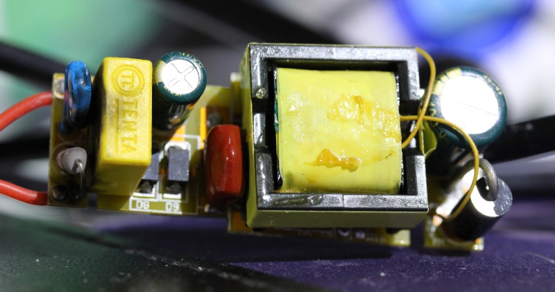
It appears to be a fairly conventional flyback converter with 4 discrete diodes as rectifier bridge, 400V rated input cap, through hole flyback transformer on top and switching transistor with controller IC on bottom side, and a larger output capacitor.

It appears that the switching transistor and controller IC both burned out, and are missing parts of their package.
The part numbers are unreadable, and I am too unexperienced with power electronics to guess them. Could someone suggest a controller IC that might be suitable as replacement? The package is SOIC-8 I believe. And what kind of (N?) switching transistor or MOSFET should I choose?
Any help is more than welcome!
I'd like to fix a burned out driver circuit for a 30W (15 x 2W) LED lamp, photographs of the charred chaos below:


It appears to be a fairly conventional flyback converter with 4 discrete diodes as rectifier bridge, 400V rated input cap, through hole flyback transformer on top and switching transistor with controller IC on bottom side, and a larger output capacitor.

It appears that the switching transistor and controller IC both burned out, and are missing parts of their package.
The part numbers are unreadable, and I am too unexperienced with power electronics to guess them. Could someone suggest a controller IC that might be suitable as replacement? The package is SOIC-8 I believe. And what kind of (N?) switching transistor or MOSFET should I choose?
Any help is more than welcome!

