Continue to Site
Follow along with the video below to see how to install our site as a web app on your home screen.
Note: This feature may not be available in some browsers.
Can any body give me 180AH lead acid battery charger circuit with float and boost feature and auto cut off when charged
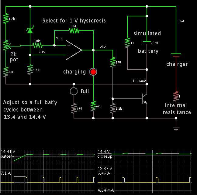
can some one you explain this circuit plz
BradtheRad : thanks for the detail .. now i am following this topology and i thing its better ? what you say ?
http://danyk.cz/nab_ab_en.html
thanks for the detail response . . above charger can charge max upto 2-3 amp . . i want to charge battery of 200Ah . is there any other way in switching topology to achieve this ??
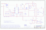
i found current mode pwm chip i thing it is better then uc3842 . . what you say ?? see the attachments
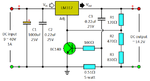
hey guys i am also looking for same i found common circuit for same as follow.
https://renewablekinabalu.blogspot.in/2013/07/homemade-12v-sealed-lead-acid-battery.html
will it work??
here is my battery