Continue to Site

Welcome to EDAboard.com

Welcome to our site! EDAboard.com is an international Electronics Discussion Forum focused on EDA software, circuits, schematics, books, theory, papers, asic, pld, 8051, DSP, Network, RF, Analog Design, PCB, Service Manuals... and a whole lot more! To participate you need to register. Registration is free. Click here to register now.

lead acid battery charge circuit with low voltage cutout

Status
Not open for further replies.

Jester

Full Member level 6
Joined
Aug 18, 2012
Messages
377
Helped
7
Reputation
14
Reaction score
7
Trophy points
1,298
Location
.
Activity points
4,754
I need to design a 12V lead acid battery charge circuit and also incorporate a low voltage cutoff circuit to prevent excessive battery discharge. I'm trying minimize part count.

One approach is to use a TI BQ24450 battery charge controller IC https://www.digikey.com/product-detail/en/BQ24450DWTR/296-24367-1-ND/2051746

And then add a cutoff circuit something like this (modified for say 10V): figure_01.gif
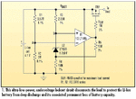
1) Does this seem like a reasonable approach?

2) Assuming maximum charge current of 1A, can anyone recommend a suitable FET for SW1?

3) In a perfect world, perhaps there is one IC that incorporates both functions, does such an IC exist?

Suggestions welcome
 

This injects 187.5mV of hysteresis above the 3.00V shutdown to enable it.

You probably want 300mV of hysteresis above a shutdown of 11.5V with a drop of <100mV on the switch or < 100mOhms RdsOn. For precision any bandgap reference will do. Even 2V LED @1mA will do or a 1 cent silicon diode with 1mA at 600mV for a reference may do with a limited temp range.

What's more important? lowest cost or fewest parts?

- - - Updated - - -

Not a common spec for 1 IC.

Generally protection is for OVP.
You could modify this OVP OCP chip for UVP only using the Vctrl divided from 11.5 to 2.5 but then no hystereis. THen use the output to bias Ictrl to add hysteresis and not turn back on until Vin rises to 11.6 or some level that does not cause motorboating on/off.

Then use a suitable Pch MOSFET.
 
  • Like
Reactions: Jester

    Jester

    Points: 2
    Helpful Answer Positive Rating
"smart FETs" by Infineon may also be worth looking into.
 
  • Like
Reactions: Jester

    Jester

    Points: 2
    Helpful Answer Positive Rating
This injects 187.5mV of hysteresis above the 3.00V shutdown to enable it.

You probably want 300mV of hysteresis above a shutdown of 11.5V with a drop of <100mV on the switch or < 100mOhms RdsOn. For precision any bandgap reference will do. Even 2V LED @1mA will do or a 1 cent silicon diode with 1mA at 600mV for a reference may do with a limited temp range.

What's more important? lowest cost or fewest parts?

- - - Updated - - -

Not a common spec for 1 IC.

Generally protection is for OVP.
You could modify this OVP OCP chip for UVP only using the Vctrl divided from 11.5 to 2.5 but then no hystereis. THen use the output to bias Ictrl to add hysteresis and not turn back on until Vin rises to 11.6 or some level that does not cause motorboating on/off.

Then use a suitable Pch MOSFET.


I prefer to minimize part count while keeping the comparator circuit <$2 (qty1)

The SEA05TR is an interesting part, I like the integrated reference. Unfortunately my circuit needs to operate down to -40°C.

With Vbatt in the 13-14V range, that seems to eliminate all of the comparators with internal reference when I do a Digi-Key search.

Perhaps there is an op amp with internal reference that can be used?
  • Vcc > 15V
  • Internal reference connected to non-inverting input
  • Push-Pull output

Searching no luck so far
 

It wouldn't take much power to raise the temp 15'C on the chip from -40'C to -25'C when below 0'C. :thinker:

But for one pc. the cost of design far exceeds the cost of the components.

Besides you also want to factor battery ESR rises sharply below -25'C also drop in Charge capacity in the design so a thermal sensor may be a good thing.

- - - Updated - - -

Not sure why D-K quoted -25'C that only affects the quoted tolerances. It will still work down to -40'C which may be acceptable tolerances for you. Your test plan with dry ice will prove this.

Datasheet for SEA05TR indicates
Tj op Junction temperature operating range -40 to 150
 

Status
Not open for further replies.

Similar threads

Part and Inventory Search

Welcome to EDABoard.com

Sponsor

Back
Top