andreidaniel
Member level 2
- Joined
- Sep 18, 2010
- Messages
- 42
- Helped
- 1
- Reputation
- 5
- Reaction score
- 2
- Trophy points
- 1,288
- Location
- Romania, Iasi City
- Activity points
- 1,818
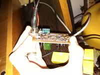
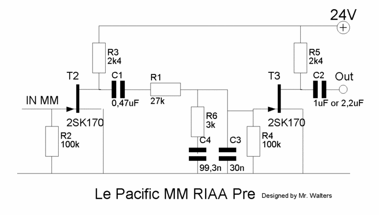
Hello guys!! Long time ago I decided o try the schematics of the Le Pacific preamplifier.

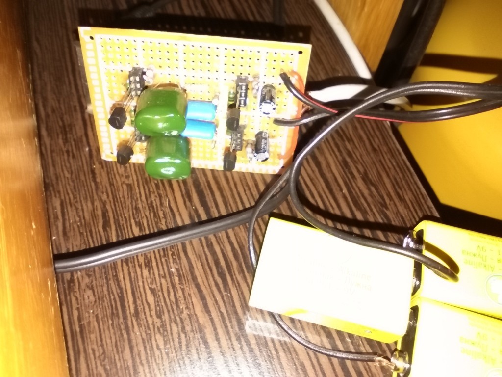
If I try to power the entire bloc from a DC source the hum is higher, so I power it from 3 x 9V battery but they don't last so much. I also placed a 220uF/50V capacitor between + and - for reducing a little the hum.
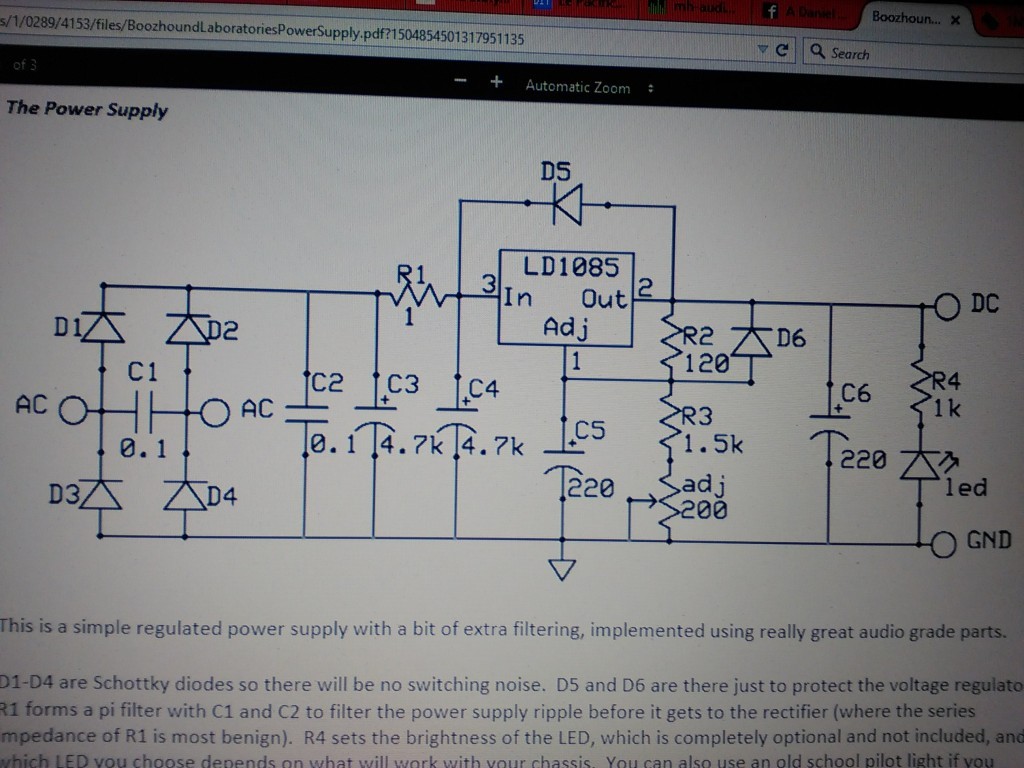
The boozhound website recommands a unique power supply for eliminating the hum.
https://boozhoundlabs.com/collections/all/products/power-supply-kit
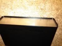
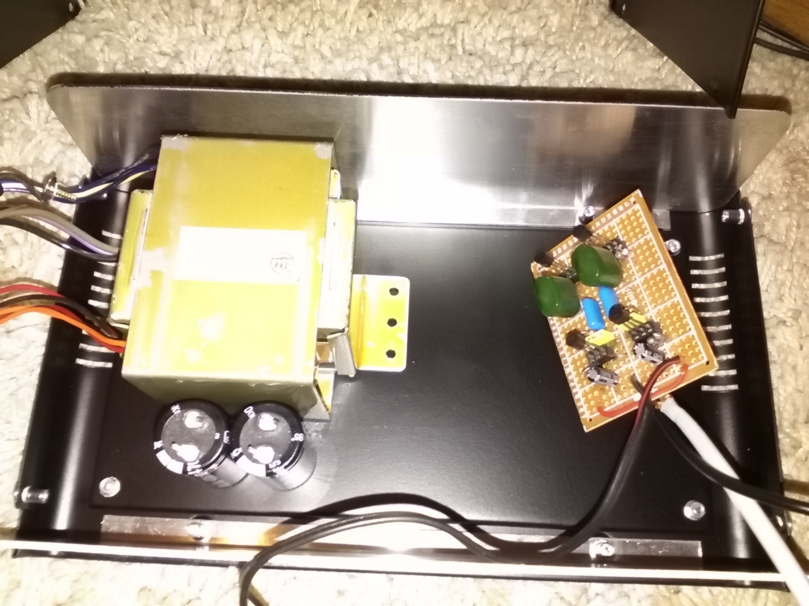
I bought yesterday this metal case for the preamplifier. Should be good a shielded metal case.
Also, I thought at some things when constructing it:
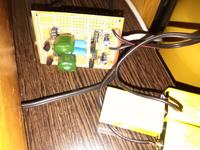
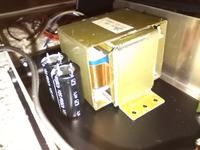
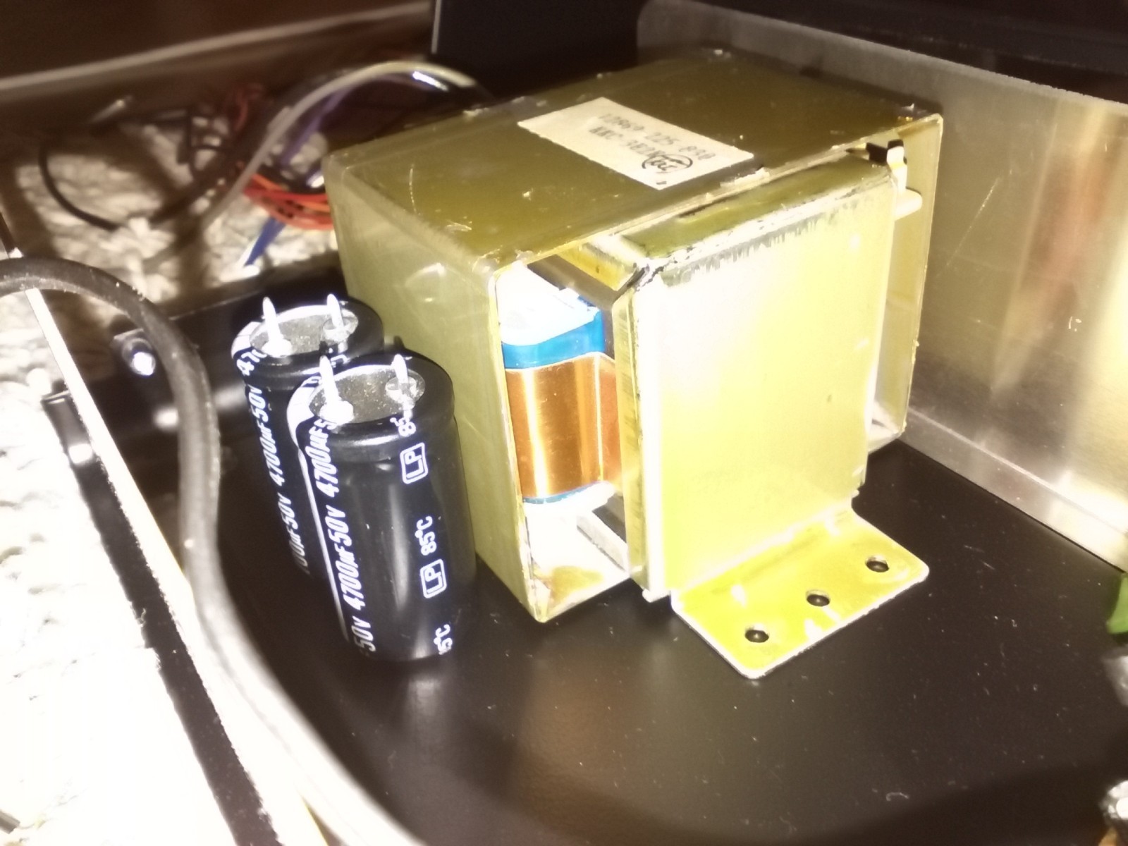
1st: I recovered a transformer from a stereo system which included radio, 2xtapes + cd and also had a phono input!! The transformer doesn't make any noise and I think that also the fact the it is shielded itself with another perpendicular cover and with the copper tape on the coils would not perturb the good functioning of the preamplifier.
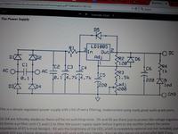
2nd: As it seems in the original power supply the author usess schottky diodes, and between those two caps of 4700uF there is a 1 ohm resistor. I am thinking that a good result could be in replacing that resistor with a small coil on the ferrite ring linke those from the PCs or notebooks power supply because the resistor has a low value and also could take the noise after. My question here is if I can replace that LD1085 with a LM317? Or LM150, 350? On the internet I saw different designs which used either LM317 or even zenner+transistors for the regulated power supply.
3rd: I'll redesing the entire board on a PCB. This is only "educational" but works fine. Something like this should appear finally:

For the rear pannel I was thinking to put 2 x RCA + 1 x 5 pin DIN for the older devices, and for the front pannel the same as rear.
If I try to power the entire bloc from a DC source the hum is higher, so I power it from 3 x 9V battery but they don't last so much. I also placed a 220uF/50V capacitor between + and - for reducing a little the hum.

The boozhound website recommands a unique power supply for eliminating the hum.
https://boozhoundlabs.com/collections/all/products/power-supply-kit
I bought yesterday this metal case for the preamplifier. Should be good a shielded metal case.

Also, I thought at some things when constructing it:
1st: I recovered a transformer from a stereo system which included radio, 2xtapes + cd and also had a phono input!! The transformer doesn't make any noise and I think that also the fact the it is shielded itself with another perpendicular cover and with the copper tape on the coils would not perturb the good functioning of the preamplifier.
2nd: As it seems in the original power supply the author usess schottky diodes, and between those two caps of 4700uF there is a 1 ohm resistor. I am thinking that a good result could be in replacing that resistor with a small coil on the ferrite ring linke those from the PCs or notebooks power supply because the resistor has a low value and also could take the noise after. My question here is if I can replace that LD1085 with a LM317? Or LM150, 350? On the internet I saw different designs which used either LM317 or even zenner+transistors for the regulated power supply.
3rd: I'll redesing the entire board on a PCB. This is only "educational" but works fine. Something like this should appear finally:
For the rear pannel I was thinking to put 2 x RCA + 1 x 5 pin DIN for the older devices, and for the front pannel the same as rear.
Last edited by a moderator: